- 16 -
DGS-TDS-N 05.09 A. B. © Electrolux
599 521 367
EN
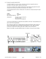
Fig. Door lock in unlocked state
2 – E Inlet unlocking
4 – Inlet lock
3 – Phase (230 V)
33/34 – Switch contacts (5 V, 100 mA)
unlocked
interlocked
As soon as a voltage of 230 V is applied to the contacts 3 and 4, the bar “A” moves to the other side
after 2 – 10 seconds and blocks the lock lever mechanically. The door cannot be opened. At the
same time, the internal contact “B” opens and disconnects the lock path. The switch contacts 33/
34 close and signal that door lock is completed. The electronic signal completes the lock signal.
Internal contact “C” closes.
For unlocking, a voltage of 230 V must be applied to contacts 2 and 3. The bar “A” moves
backwards and releases the lock lever. The door can be opened provided that the contact f11
(Klixon) is closed.
Summary of Contents for COOKING
Page 32: ... 32 DGS TDS N 05 09 A B Electrolux 599 521 367 EN 7 2 Example circuit diagram OVC 1000 ...
Page 33: ... 33 DGS TDS N 05 09 A B Electrolux 599 521 367 EN 7 3 Example circuit diagram OVC 2000 ...
Page 34: ... 34 DGS TDS N 05 09 A B Electrolux 599 521 367 EN 7 4 Example circuit diagram SOEC ...
Page 35: ... 35 DGS TDS N 05 09 A B Electrolux 599 521 367 EN 7 5 Example circuit diagram Prisma ...
Page 36: ... 36 DGS TDS N 05 09 A B Electrolux 599 521 367 EN 7 6 Example circuit diagram HOC 2000 ...
Page 37: ... 37 DGS TDS N 05 09 A B Electrolux 599 521 367 EN 7 7 Operative Equipment Overview ...
Page 38: ... 38 DGS TDS N 05 09 A B Electrolux 599 521 367 EN Changes Pages 26 Chapter 6 1 changed ...


