background image

Summary of Contents for DC6-8HP Q Series

Page 1: ...Installation manual Drying Cabinet DC6 8HP_Q Original instructions 427001229 EN 2022 05 25 ...

Page 2: ......

Page 3: ...on kit 9 4 3 Installation of upper part 10 5 Positioning Attachment 12 5 1 Ventilating the room 12 5 2 Attachment to the wall 13 6 Electrical connection 14 6 1 Network Functions 15 7 Connection to floor drain 17 8 Function check 18 9 Disposal information 19 9 1 Disposal of appliance at end of life 19 9 2 Disposal of packing 19 The manufacturer reserves the right to make changes to design and compo...

Page 4: ......

Page 5: ...supervision or instruction con cerning use of the appliance in a safe way and understand the hazards involved Children shall not play with the appliance Cleaning and user maintenance shall not be made by children without supervision Additional requirements for other countries This appliance is not intended for use by persons including children with reduced physical sensory or mental ca pabilities ...

Page 6: ...manual 2 Technical data 2 1 Dimensions drawing K D C F G E A 1 H J I 2 B fig W01385 A B C D E F G H I J K mm 1195 673 2061 424 1080 90 2079 436 452 809 850 1 Control panel 2 Condensation nipple 18 mm 3 m hose included ...

Page 7: ...he ventilation need Climate zone building parameters room size etc Connections Connection condensation Plastic hose dim 18 mm 3 m hose included Heat pump Type of refrigerant R134A Amount of refrigerant kg 1 0 Fluorinated greenhouse gases This product contains fluorinated greenhouse gases GWP 1430 CO2 equivalent 1 43 t Leak test 28 bar Hermetically sealed Energy consumption and drying times Drying ...

Page 8: ...inet is delivered as two units on the same pallet one upper part that includes the dehumidifier unit and one fully assembled cabinet frame 1 3 180 kg 1400 1220 1877 704 2 fig W01386 1 Transport pallet 2 Packaging upper part 3 Packaging frame ...

Page 9: ... materials such as plastic and styrofoam should be kept out of reach of children 4 2 Installation kit 1 2 3 4 5 6 7 8 fig W01372 1 Screw M8x20 4 See page 10 2 Screw 4x9 5 SHEETtracs 2 See page 10 3 Screw M8x16 2 See page 12 4 Angle bracket 2 See page 12 5 Lifting tube 4 See page 10 6 Fastening screw for wall 2 washer 2 plastic plug 2 See page 12 7 Condensation hose in roll 1 See page 14 8 Brush 1 ...

Page 10: ...ring setup as well Upper part as seen from behind 2 1 fig W01387 1 Hose nipple 2 Lamp 3 Door cable Lower part with door cable connected 3 fig W01374A The fully assembled right door has an installed door cable 3 connected to the control panel in the door Bend it away so it is not damaged when the upper part is placed on the lower part The cable is connected to the terminal block as described in the...

Page 11: ...pper part onto the lower part and secure it with the four provided M8x20 screws and the two 4 x 9 5 SHEETtracs screws for the air duct as illustrated Pull out the air tubes and refit the cover plugs Reinstall the lamp and lamp lens After setup store the air tubes at a suitable spot for future use 2 3 4 A A B B 1 fig W01375A 1 Fastening screw for upper part M8x20 4 2 Fastening screw 4x9 5 SHEETtrac...

Page 12: ...1 Ventilating the room When the machine is in operation the room temperature increases Due to this the room must have sufficient ventilation All sources introducing heat into the same room requires to be considered when dimensioning the ventilation Heat sources could for example be more tumble dryers drying cabinets washers ironers radiators etc The combination of several sources for heat introduc...

Page 13: ...ng The installation kit contains two angle brackets that are mounted on the upper part of the drying cabinet as illustrated Use the provided screws The brackets have grooves for adjustment to the wall Secure the cabinet to the wall The installation kit contains a fastening screw and plastic plugs fig W01389 ...

Page 14: ...to 400V 3N AC Connection is only permitted to a mains with maximum impedance of 0 239 ohm Total power 3 5 kW Fuse 13 A Remove the front plate The front plate is secured with four screws at the top and four screws at the bottom Install a 5 wire connecting cable to the terminal block on the PCB as indicated in the wiring diagram Route the ca ble to and through the marked bushing in the roof plate Th...

Page 15: ...program buttons press Stop Use the program buttons to move to Parameter 117 and enter the parameter using the Stop button Select the baud rate that matches the setting in ELS Vision 0 off 1 2400 bps 2 4800 bps 3 9600 bps Use the Stop button to exit the parameter Then access parameter 118 and set network address 1 127 To confirm the new settings Press the Stop button and then Butterfly Connecting t...

Page 16: ...meter value to 1 This will activate the cabinet for network use Use the Stop button to exit the parameter To confirm the new settings Press the Stop button and then Butterfly Restore factory settings To restore the electronics to factory settings Press the Stop button and then press both program buttons The display shows FACT DEFS ...

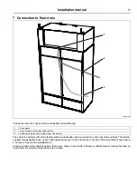
Page 17: ... The cabinet is delivered from the factory with a condensation drain connection on the rear of the cabinet Thread the supplied condensation hose on the hose nipple and route it to the floor drain Thread on the hose without hose clip A 3 m hose is found in the installation kit In the rear edge of the cabinet s sides there are 2 holes on each side Choose a suitable hole for routing the hose so that ...

Page 18: ...henever a repair has been made a function check must be performed before the appliance can be used again Select any program and check that the drying cabinet is heating and that there are no odd noises Ready for use If all tests are OK the appliance is now ready for use If any of the tests fail or deficiencies or faults are detected please contact your local service organization or supplier ...

Page 19: ...cycled and that the refrigerator and heat pump components are special waste assimilable with urban waste The symbol on the product indicates that this product should not be treated as domestic waste but must be correctly disposed of in order to prevent any negative consequences for the environment and human health For further information on the recy cling of this product contact the local dealer o...

Page 20: ...Electrolux Professional AB 341 80 Ljungby Sweden www electroluxprofessional com ...

Reviews: