64
Fixing
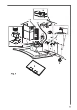
• Trace the median line on the wall, choose a comfortable height for
the user and trace it on the wall to make montage easier
(1-2)
.
• Determine the
X
and
Y
dimensions and mark the position of the two
holes with a pencil. Then carry out the perforation (2 x Ø 12 mm);
insert the two hooks with dowels
(3)
.
• Remove the fat filter
(4)
, hang the hood up, adjust its horizontal po-
sition with the adjustment screws
(5)
.
• Mark the position of the 2/4 holes on the wall
(6)
.
Remove the hood and carry out the perforation (2/4 x Ø 8 mm). In-
sert the dowels into the holes.
• Fix the flue support bracket
(7A – Suction version)
or the deflector
(7F – Filtering version)
with the Ø 8 mm dowels and the Ø 5x45
mm screws at 3-4 mm distance from the ceiling with the hood cen-
tred and perfectly horizontal.
• Hand the hood up again, fixing it definitively
(8)
with the screws (2/4
x Ø 5x45 mm).
• Fix the reduction tube
(9)
above the hood with two Ø 3 x 9 mm
screws.
• Use a tube long enough to reach the outside
(10)
or the deflector
(7F – Filtering version).
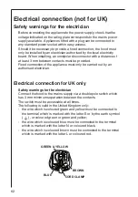
• Connect the electricity
(11)
(see “Electric connection” chapter).
• Apply the flue
(12)
and fix it to the support bracket with 2 Ø 3x9 mm
screws or to the deflector with 4 Ø 3.5x13 mm screws. Let the lower
part of the flue slide down and apply the upper part over the hood
(13)
.
• Mount the fat filter.
Summary of Contents for DD 6591
Page 17: ...17 Y 1 3 3 6 6 6 6 7A 8 10 12 2 X X Y S G 4 9 11 13 5 7F Bild 8 ...
Page 32: ...32 Y 1 3 3 6 6 6 6 7A 8 10 12 2 X X Y S G 4 9 11 13 5 7F afb 8 ...
Page 49: ...49 Y 1 3 3 6 6 6 6 7A 8 10 12 2 X X Y S G 4 9 11 13 5 7F Fig 8 ...
Page 65: ...65 Y 1 3 3 6 6 6 6 7A 8 10 12 2 X X Y S G 4 9 11 13 5 7F Fig 8 ...
Page 66: ...66 ...
Page 67: ...67 ...
Page 68: ...LI2ZAA Ed 08 06 ...

