background image


EN 

1

17 

RECOMMENDATIONS AND SUGGESTIONS


INSTALLATION 

•  The manufacturer will not be held liable for any damages resulting from 

incorrect or improper installation. 

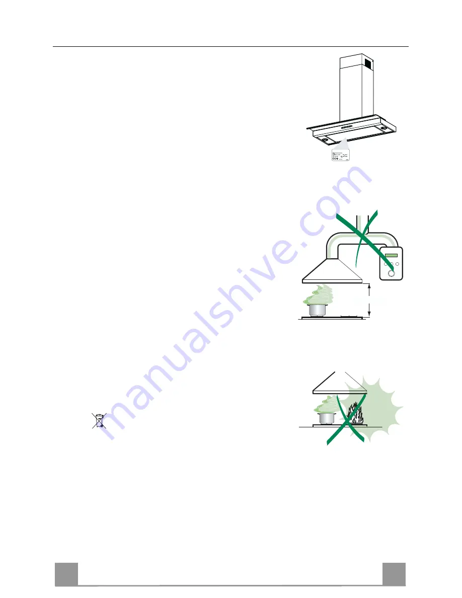
•  The minimum safety distance between the cooker top and the extractor 

hood is 650 mm. 

•  Check that the mains voltage corresponds to that indicated on the rating 

plate fixed to the inside of the hood. 

•  For Class I appliances, check that the domestic power supply guarantees 

adequate earthing. 

  Connect the extractor to the exhaust flue through a pipe of minimum di-

ameter 120 mm. The route of the flue must be as short as possible. 

•  Do not connect the extractor hood to exhaust ducts carrying combustion 

fumes (boilers, fireplaces, etc.). 

•  If the extractor is used in conjunction with non-electrical appliances (e.g. 

gas burning appliances), a sufficient degree of aeration must be guaran-
teed in the room in order to prevent the backflow of exhaust gas. The 
kitchen must have an opening communicating directly with the open air in 
order to guarantee the entry of clean air.   

USE 

•  The extractor hood has been designed exclusively for domestic use to 

eliminate kitchen smells. 

•  Never use the hood for purposes other than for which it has ben designed. 
•  Never leave high naked flames under the hood when it is in operation. 
•  Adjust the flame intensity to direct it onto the bottom of the pan only, mak-

ing sure that it does not engulf the sides. 

•  Deep fat fryers must be continuously monitored during use: overheated oil 

can burst into flames. 

•  The hood should not be used by children or persons not instructed in its 

correct use. 


MAINTENANCE 

•  Switch off or unplug the appliance from the mains supply before carrying 

out any maintenance work. 

•  Clean and/or replace the Filters after the specified time period. 
•  Clean the hood using a damp cloth and a neutral liquid detergent. 

The symbol 

 on the product or on its packaging indicates that this product 

may not be treated as household waste. Instead it shall be handed over to the 
applicable collection point for the recycling of electrical and electronic equipment. 
By ensuring this product is disposed of correctly, you will help prevent potential 
negative consequences for the environment and human health, which could oth-
erwise be caused by inappropriate waste handling of this product. For more de-
tailed information about recycling of this product, please contact your local city 
office, your household waste disposal service or the shop where you purchased 
the product. 


650 mm min.


Summary of Contents for DD9691-M

Page 1: ...e da incasso con schermo piatto Estraibile Hottes aspirantes encastrables à visière plate Inbouw wasemkappen met plat scherm Montage und Gebrauchsanweisung Installation and Operating Instructions Istruzioni di montaggio e per l uso Instructions de montage et mode d emploi Montage en gebruiksaanwijzing ...

Page 2: ...DE 2 2 Bedienungsanleitung INHALTSVERZEICHNIS EMPFEHLUNGEN UND HINWEISE 7 CHARAKTERISTIKEN 8 MONTAGE 9 BEDIENUNG 13 WARTUNG 14 ...

Page 3: ...EN 3 3 Instructions Manual INDEX RECOMMENDATIONS AND SUGGESTIONS 17 CHARACTERISTICS 18 INSTALLATION 19 USE 23 MAINTENANCE 24 ...

Page 4: ...IT 4 4 Libretto di Istruzioni INDICE CONSIGLI E SUGGERIMENTI 27 CARATTERISTICHE 28 INSTALLAZIONE 29 USO 33 MANUTENZIONE 34 ...

Page 5: ...FR 5 5 Manuel d Instructions SOMMAIRE CONSEILS ET SUGGESTIONS 37 CARACTERISTIQUES 38 INSTALLATION 39 UTILISATION 43 ENTRETIEN 44 ...

Page 6: ...NL 6 6 Gebruiksaanwijzing INHOUDSOPGAVE ADVIEZEN EN SUGGESTIES 47 EIGENSCHAPPEN 48 INSTALLATIE 49 GEBRUIK 53 ONDERHOUD 54 ...

Page 7: ...e hood for purposes other than for which it has ben designed Never leave high naked flames under the hood when it is in operation Adjust the flame intensity to direct it onto the bottom of the pan only mak ing sure that it does not engulf the sides Deep fat fryers must be continuously monitored during use overheated oil can burst into flames The hood should not be used by children or persons not i...

Page 8: ...ange ø 150 120 mm 10 a 1 Damper 10 b 1 Adapting ring ø 120 125 mm 14 1 2 Air Outlet Connection Extension 15 1 Air Outlet Connection 26 1 Glass Ref Q ty Installation Components 7 2 1 2 Upper Chimney Section Fixing Brackets 7 3 1 Air Outlet Connection Support 11 6 Wall Plugs 12a 6 Screws 4 2 x 44 4 12c 6 Screws 2 9 x 9 5 Q ty Documentation 1 Instruction Manual 2 1 2 2 2 12c 12a 7 2 1 11 11 12a 9 7 3...

Page 9: ... the first bracket X height of the upper chimney section supplied aligning the centre notch with the vertical line Mark the wall at the centres of the holes in the bracket Mark a reference point as indicated at 116 mm from the vertical reference line and 320 mm above the horizontal reference line Repeat this operation on the other side Drill ø 8 mm holes at all the centre points marked Insert the ...

Page 10: ... version connect the hood to the chimney using either a flexible or rigid pipe ø 150 or 125mm the choice of which is left to the installer To install a ø 150 To install the dumper 10a Fix the pipe in position using sufficient pipe clamps not supplied To install a ø 125 To install a ø 125 mm air exhaust connection insert the redu cer flange 9 on the dumper 10a To install the Adapting ring 10b Fix t...

Page 11: ... has been installed Ensure that the activated charcoal filters have been inserted ø 150 14 1 15 ELECTRICAL CONNECTION Connect the hood to the mains through a two pole switch hav ing a contact gap of at least 3 mm Remove the grease filters see paragraph Maintenance being sure that the connector of the feeding cable is correctly inserted in the socket placed on the side of the fan Flue assembly Uppe...

Page 12: ...2 Glass Assembly Unscrew Vx to fix the glass Please set the glass 26 on the Body Hood being care ful that both supports are correctly positioned Fix the glass with the two screws Vx previously re moved Vx 26 ...

Page 13: ...ed 3 delay 10 minutes The recommended delay time can be changed by pressing this key in sequence 5 10 15 20 25 e 30 minutes When the se lected time is over the appliance will shut down automatically By pressing this key and selecting option 0 this function will deactivate Shows F Indicates that the metal grease filters saturation alarm has been triggered and the filters need to be washed The alarm...

Page 14: ...y need to be washed when F sign appears on the display or in any case every 2 months or even more frequently in case of particularly intensive use of the hood Alarm reset Switch off the hood and the lights Press the D key till the display is unlit Cleaning the filters Pull the comfort panels to open them Remove the filters one by one pushing them towards the back side of the hood unit and simultan...

Page 15: ...ting rectangles appear on the display Within 3 seconds press the B key until a flashing confirmation appears on the dispaly 2 flashes with C charcoal filter saturation alarm ACTIVATED 1 flash with C charcoal filter saturation alarm DEACTIVATED REPLACING THE CHARCOAL FILTER Reset of the alarm signal Switch off the hood and the lighting Press the D key until the display is unlit Replacing of the fil...

Page 16: ...ert the two pins properly into the housings on the lamp holder Replace the snap on lamp cover Lower Halogen Lights 20 W Find the cut side of the snap on cover ring by pressing gently toward the centre of the spot light it will be released Remove the snap on cover and the glass being careful not to drop it Remove the halogen lamp from the lamp holder by pulling gently Replace the lamp with a new on...

Page 17: ......

Page 18: ......

Page 19: ......

Page 20: ... Veuillez donner les indications suivantes à notre service après vente en cas de panne Qualora constataste un difetto vi preghiamo di comunicare i seguenti dati al nostro servizio tecnico assistenza clienti Geef onze klantenservice bij een storing de volgende gegevens op E Nr 610 F Nr AEG Hausgeräte GmbH Postfach 1036 D 90327 Nürnberg Copyright by AEG Dir 89 336 CEE 73 23 CEE 93 68 CEE ...

Reviews: