SOI/TD 2005-2 PR
/26
599 36 83-66
12
7.3 Power supply and programme selection
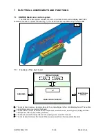
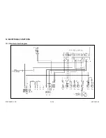
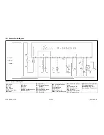
The main board is powered by the closure of contacts. The connectors used are B2 (neutral) and B1
(line).
The control/display board (user interface) is powered at 220V by the main board.
When the door is closed, the main board detects the closure of the contacts of the switch (IP) across
connectors C1-C3 and starts the washing programme.
When the door is opened, the power loads are disconnected from the power supply and the cycle is
paused.
7.4 Fill
circuit
7.4.1 Level and anti-overflow pressure switch
•
The level of water introduced into the appliance is determined by
the level pressure switch.
•
The
anti-overflow pressure switch ensures that the level of water does not exceed the safety threshold
(causing overflow from the door).
7.4.2 Fill
system
The water fill solenoid valve is powered by the electronic board via the connector D7, by the door
switch (IP) and the anti-flooding microswitch (DA).
The level of water in the sump is monitored by the pressure switch (RL). The electronic board constantly
monitors the status of the pressure switch via a “sensing” line connected to connector D5:
EMPTY if the contacts are closed on 1-2
FULL if the contacts are closed on 1-3
7.4.3 Anti-flooding
device
Intervention of the anti-flooding device causes the contacts of the microswitch (DA) to open, thus
disconnecting the solenoid valve from the power supply.
7.4.4 Intervention of the anti-overflow system
If the anti-overflow pressure switch (PA) should intervene, the closure of the contact on FULL (1-3)
powers the drain pump (PS). The pump remains in operation until the contact returns to EMPTY (1-2).
If the door is opened or the appliance is switched off, the drain pump is deactivated
.
7.5 Control of water fill phase
The quantity of water necessary to carry out the washing cycle is determined exclusively by the
closure of the electrical contact of the pressure switch, which changes from EMPTY to FULL. This system
ensures that, if the pressure switch re-opens on EMPTY, further water is introduced until it returns to FULL.
The water fill phase consists of the following sub-phases:
7.5.1 Static
fill
With the motor switched off, the fill solenoid valve is energized and water is introduced into the
appliance until the pressure switch signal switches to FULL.
7.5.2 Dynamic
fill
The dynamic fill is obtained by switching on the washing pump whose rotation causes the pressure
switch to switch to EMPTY. Subsequently, the fill solenoid valve is energized and water is introduced until
the switch returns to FULL.
The speed of rotation of the motor determines the quantity of water introduced, since the electronic
control system switches on the washing pump at a rotation speed of
2600-2800 rpm
.
7.5.3 Level
stability
control
The hydraulic circuit operates with maximum efficiency when the pressure switch signal remains
stable on FULL. In practise, the quantity of water circulating in the sump allows the motor to run without
speed fluctuations caused by cavitation.
When the pressure switch signals FULL, the fill solenoid valve switches.

