
SOI/TD 2005-2 PR
/26
599 36 83-66
5
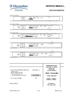
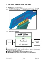
1 Purpose of this manual
The purpose of this manual is to provide service personnel (who already have the basic knowledge
necessary for repairing dishwashers) with information on dishwashers equipped with the EDW503
electronic control system, which are produced in the Solaro (MI - Italy) factory.
The EDW503 control system consists of a main circuit board and a control/display board. Both
boards are housed in a single plastic container. It is used in some “DIVA” models.
This Manual describes:
•
General
characteristics
•
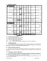
Control panel and programmes
•
Technical
characteristics
•
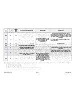
Guide to diagnostics
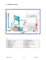
For more detailed information regarding the hydraulic circuits and the structural characteristics of the
appliances, refer to the Service Manual for presentation of the “DIVA” structure (publication number
599 35 55–25, 599 36 09-90
).
2 PRECAUTIONS
Electrical appliances must be serviced only by qualified Service Engineers.
Always remove the plug from the power socket before touching internal
components.
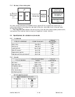
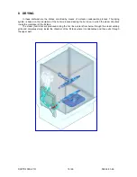
3 GENERAL
CHARACTERISTICS
Power supply
⇒
230 V / 50 Hz (limits 187
÷
254 V)
Total power absorption
⇒
2200 W (Resistance 2000W)
Mains water supply
⇒
Pressure Min. / Max. 5
÷
80 N/cm²
Capacity
⇒
9/12 place settings (45/60 cm)
Consumption (prog. BIO):
Water
⇒
Lt. 14
Energy
⇒
KWh 0,8
Duration of cycle
⇒
136’-143’ (45/60 cm)
Controls
-
ON/OFF
⇒
On/Off function button
-
Programme
start
⇒
By button Start/Reset
-
Programme
selection
⇒
By knob (n°3÷5 programmes)
-
Option
selection
⇒
By 1 button
-
Display
⇒
Leds
-
Washing system
⇒
Continuous (2600-2800 rpm)
Water fill level control
⇒
Pressure Software
Water heating
⇒
Heating element enclosed in tube (2000 W)
Temperature control
⇒
NTC Temperature sensor
Drying systems
⇒
Active
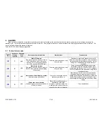
Safety systems / Alarms
⇒
Total protection (hyd Software)


