background image

15


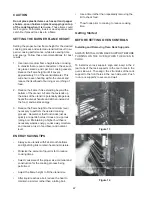
over the cooktop and create a fire hazard.

•   Do not cover the burners and grates with 


anything except properly selected utensils. 


Decorative covers should not be used.

•   Do not heat unopened food containers such   


as baby food jars and cans. Pressure buildup  


may cause  the container to burst and cause 


injury.

•   Do not use abrasive or caustic cleaners or 


detergents on this appliance, as these may    


cause permanent damage. Do not use aerosol  


cleaners, as these may be flammable or cause  


corrosion of metal parts.

•   Do not use or attempt to use this appliance in the  


event of a power failure.

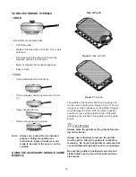
•   Do not slide cookware across the grates. Sliding  


may damage the finish of the grates. Lift utensils  


to reposition them.

 wARNING 

Severe shock, or damage to the appliance may occur 

if the appliance is not installed by a qualified installer 

or electrician.


wARNING 

NEVER

 use this appliance as a space heater to heat or 

warm the room. Doing so may result in carbon monox-
ide poisoning and overheating of the appliance.

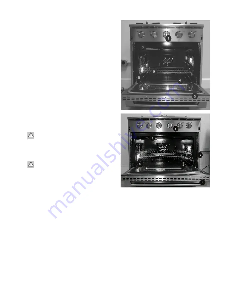
Feature Overview

Before  using  your  range,  become  familiar  with  the 
features and control panel layout. See Figure 22  for a 
detailed control panel layout for your model.

1.  Control Panel 

     2.    Infrared Broiler

3.  Convection Fan 

     4.    Bake Burner

5.  Oven Door   

     6.    Oven Racks

7.  Oven Rack Supports     8.    Oven Rack Glides

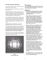
PROPER bURNER ADJUSTMENTS

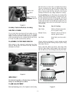
The color of the flame is the key to proper burner adjust

-

ment.  A good flame is clear, blue and hardly visible in a 

well-lighted room.  Each cone of flame should be steady 

and sharply defined.  Adjust or clean burner if flame is 

yellow-orange.  To clean burner, see instructions under 

General care & cleaning.

Summary of Contents for E30GF74GPS - 30" Pro-Style Gas Range

Page 1: ...Publication 5995496584 August 2007 P N 316439280 Technical Service Manual 30 And 36 Inch All Gas Range Models E30GF74GPS E36GF75GPS E36GF76GPS ...

Page 2: ...y residual gas to dissipate for 10 to 20 minutes 3 Never interfere with the proper operation of any safety device 4 Use only replacement parts cataloged for this appliance Substitutionsmaydefeatcompliancewithsafetystandards set for home appliances 5 GROUNDING The standard color coding for safety ground wires is green or green with yellow stripes Ground leads are not to be used as current carrying ...

Page 3: ...iguration 16 Burner base head cap 16 Burner igniters 16 Cooktop features surface cooking 17 Control knobs 17 Placement of burner grates 17 Flame adjustment 17 For most cooking 17 For deep fat frying 17 Surface cooking utensils 18 Using the accessory griddle some models 18 Using the integrated griddle 19 To grill food 19 To clean 19 Using the wok stand 19 To properly position the wok stand 20 Flat ...

Page 4: ... convection mode temperature 28 Broiling 28 Preheating 28 To broil 28 Setting broil 29 To set the oven to broil 29 Broiling tips 29 Broiling times 29 Oven broiling recommendations 29 Broiling clean up tips 30 Care and cleaning 30 Oven light 30 To replace the light bulb 30 Cleaning tips for range oven 30 Porcelain enamel oven 30 General cleaning 31 Cleaning the oven bottom 31 Cleaning tips for rang...

Page 5: ...ven and griddle burner 55 Oven circuit 56 Griddle circuit 57 Electrical operation of the convection fan motor 58 SECTION D TROUBLESHOOTING 59 Electrical components will not operate 60 Burner ame too large and yellow 60 Burner ame too small 60 Flame goes out when the valve is turned to the simmer position 60 Top burners not burning properly 60 One top burner not burning properly 61 Top burner valve...

Page 6: ...n bottom 75 Removing oven lights 75 Removing bake burner baf e 75 Removing the convection fan cover 75 Removing the convection fan blade 76 Removing the convection fan insulation cover 76 Removing the convection fan motor and mounting bracket 76 Removing the convection fan motor from the mounting bracket 77 Removing the rear panel 77 Removing the pressure regulator 77 Removing the top burner ignit...

Page 7: ...dels with built in griddle 87 Removing the griddle ori ce 36 inch models with built in griddle 88 Removing the griddle igniter 88 Removing the griddle igniter bracket 89 Removing the griddle burner 89 Removing the center divider 30 inch models 89 Removing the drip pans 90 Removing the oven thermostat 90 Removing the simmer burner ori ce assembly 91 Removing the top burner ori ce assembly 91 Releas...

Page 8: ...ing facility On the frond framed between the oven door and kick plate 4 Burner btu rating refer to serial name plate Model No E30GF74GPS E36GF75GPS E36GF76GPS 3 GAS AND ELECTRIC REQUIREMENT TABLE Electrical Circuit 120 VAC 60 Hz 120 VAC 60 Hz 120 VAC 60 Hz Total Connected 5A 8A 5A Gas Type Natural Natural Natural Manifold Pressure Water Column Inches 5 5 5 Minimun Gas Supply Water Column Inches 6 ...

Page 9: ...9 sample wiring diagram always refer to the wiring diagram with the product ...

Page 10: ...10 WIRING DIAGRAM MODEL E36GF76GPS sample wiring diagram always refer to the wiring diagram with the product ...

Page 11: ...11 WIRING DIAGRAM MODEL E36GF75GPS sample wiring diagram always refer to the wiring diagram with the product ...

Page 12: ...eceipt together in a safe place for further reference SECTION A Use Care Guide Finding Information PLEASE READ AND SAVE THIS GUIDE Thank you for choosing Electrolux the new premium brand in home appliances This Use Care Guide is part of our commitment to customer satisfaction and product quality throughout the service life of your new appliance We view your purchase as the beginning of a rela tion...

Page 13: ...ce Immediately turn off the gas supply at the shut off valve disconnect electrical power to the appliance at the fuse or junction box and contact the gas supplier or qualified appliance technician Ensure that the appliance is used only by those individuals who are able to operate it properly Use the appliance only for cooking tasks expected of a home appliance as outlined in this manual Properly c...

Page 14: ... steam escape before looking or reaching into the oven Position oven racks in desired locations when the oven is cool If a rack must be repositioned after the oven is already hot be certain that potholders are used In the event that a burner flame goes out and gas escapes turn off the gas control and open a window or door Wait at least 5 minutes before attempting to use the cooktop or oven CAUTION...

Page 15: ...evere shock or damage to the appliance may occur if the appliance is not installed by a qualified installer or electrician WARNING NEVER use this appliance as a space heater to heat or warm the room Doing so may result in carbon monox ide poisoning and overheating of the appliance Feature Overview Before using your range become familiar with the features and control panel layout See Figure 22 for ...

Page 16: ... BASE HEAD CAPS The burner heads spread the flame evenly around the burner perimeters The burner heads must seat properly in the burner bases to enable proper cooktop operation To ensure proper seating the burner heads are keyed using a hole which aligns with the ignitor BURNER IGNITERS A burner igniter is located on each gas burner base When a control knob is rotated more than 90 degrees counterc...

Page 17: ... flame size for various types of cooking The size and type of utensil used and the amount of food being cooked will influence the setting needed for cooking For deep fat frying use a thermometer and adjust the surface control knob accordingly If the fat is too cool the food will absorb the fat and be greasy If the fat is too hot the food will brown so quickly that the center will be undercooked Do...

Page 18: ...RY GRIDDLE SOME MODELS Side with grill Figure 6 Side with grill Figure 7 Flat side The griddle is intended for direct food cooking and can be used on both sides Figures 6 and 7 Do not use pans or other cookware on the griddle Doing so could damage the finish With the grate in position over the burner set the griddle on top of the grate positioning the notches in the griddle over the grate fingers ...

Page 19: ...E Discoloration of the grill cooking surface is normal USING THE WOK STAND The Wok Stand provided with your cooktop is designed to allow round bottomed woks to be used It is recom mended that you use a 14 inch diameter 35 5 cm or less Wok Also using the front burners with the wok stand will produce the best results If properly posi tioned the Wok Stand will not slide off the grate CAUTION Always u...

Page 20: ...long periods of time or melting chocolate With the grate in position over the burner set the simmer plate on top of the grate centering the plate over the grate fingers See Figure 11 Then place the utensil on the simmer plate The Simmer Plate is to be used by setting the burner to its lowest setting The Simmer Plate is intended to be used for simmering only The Simmer Plate must be removed when co...

Page 21: ...es for any gas to dissipate then repeat the lighting procedure Burner igniters must always be kept clean and dry to function properly Due to the reignition feature dirty or wet igniters will result in constant sparking even if there is a flame present Additionally igniters will spark automatically if the flame is distorted by a draft or by a cooktop ventilation system Eliminate the draft or reduce...

Page 22: ...ight to the minimum level necessary to perform the desired cooking process Remember that food cooks just as quickly at a gentle boil as it does at a vigorous rolling boil Maintaining a higher boil than is necessary wastes energy cooks away moisture and causes a loss in food flavor and nutrient level ENERGY SAVING TIPS Always use utensils with flat smooth bottoms and tight fitting lids to retain he...

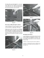
Page 23: ...Lift up the rack off the oven rack glides To install an oven rack locate the two pinholes in the small plate at the front corner of the rack Position the back of the rack on the rack glides and drop to pinholes over the pins on the rack glides Figure 16 Figure 17 Figure 18 Arranging Oven Racks ALWAYSARRANGE OVEN RACKS WHEN THE OVEN IS COOL PRIOR TO OPERATING THE OVEN Three chrome plated Smooth Gli...

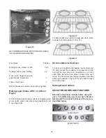
Page 24: ...etting Oven Controls SELECTOR KNOBS AND FUNCTIONS Read the instructions carefully before using the oven For satisfactory use of your oven become familiar with the various functions of the oven as described below E30GF74GPS E36GF75GPS Figure 19 RECOMMENDED RACK POSITIONS FOR BROIL ING BAKING AND ROASTING Food Rack Position Broiling meats chicken or fish 3 4 5 Cookies cakes pies muffins 2 3 Frozen p...

Page 25: ... preheat Once the oven temperature reaches 350 F the oven indicator light will turn off The oven indicator light will cycle on and off until the Bake selector knob is turned to the OFF position To change the baking temperature example 350 F to 425 F 1 After the oven is already been set at 350 F and the oven temperature needs to be changed to 425 F turn the temperature control knob to 425 F The ove...

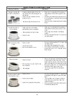
Page 26: ...sizes that will permit 2 to 4 of air space on all sides when placed in the oven Use a medium weight aluminum baking sheet Allow oven to preheat to the selected temperature before placing food in the oven Use proper rack position for baking needs Set oven temperature 25 F lower than recommended Set oven teemperature 25 F lower than recommended Used pan size suggested in recipe Used proper rack posi...

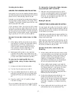
Page 27: ...rned to the OFF position To change the Convection Bake tempera ture example 325 F to 400 F 1 After the oven has already been set to 325 F and the oven temperature needs to be changed to 400 F turn the Bake selector knob to 400 F When the oven temperature reaches 400 F the oven indicator light will turn off Baking Problems CONVECTION BAKING AND ROASTING To roast meats and poultry the Convection mod...

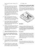
Page 28: ...l To set oven for roasting with the con vection mode using a recipe requiring 350 F 1 Arrange oven racks to desired position 2 Turn Oven selector knob to 350 F 3 The oven indicator light will turn on and the oven will begin to heat Once the oven temperature reaches 350 F the oven indicator light will turn off 4 Press fan switch to the On position to begin convection cooking Once the oven reaches 3...

Page 29: ...If preheating the broil burner first position the broiler pan with food after 3 Turn selector knob to Broil The oven light will remain on until the selector knob is turned to the off position or the temperature control knob is turned to the off position BROILING TIPS The broiling pan and its insert allow dripping grease to drain and be kept away from the high heat of the broiler NOTE DO NOT use th...

Page 30: ...he oven The light assembly consists of a removable lens cover and 50 watt 120VAC halogen bulb as well as a light fixture housing Light bulb re placement is considered to be a homeowner mainte nance operation To replace the light bulb 1 Turn off the power at the main power supply 2 Remove rack supports in order to access light housing 3 Remove the lens cover from the housing by pulling straight out...

Page 31: ...aces The cleaner can damage these surfaces Cleaning the Oven Bottom The oven bottom is porcelain enamel and can be removed for easier cleaning Clean using hot soapy water a mild abrasive cleanser a soap filled abrasive pad or oven cleaner following manufacturer s instruc tions CLEANING TIPS FOR RANGE COOKTOP No maintenance other than the Care and Cleaning identified in this Use Care Manual should ...

Page 32: ...water and hand dishwashing liquid Grates are dishwasher safe Burner caps should not be cleaned in the dishwasher Stubborn stains may be removed by applying full strength all purpose cleaning sprays If you are unable to locate these cleaning compounds please phone the Electrolux Customer Service Department for a referral Mildly abrasive cleaners or applicators such as soap filled steel wool pads ma...

Page 33: ... a warm solution of hand dishwashing liquid and water then rinse well with clean water Dry the burner thoroughly The same cleaning instructions apply to the buner heads and burner caps Stubborn stains may be removed by applying a metal polishing compound If you are unable to locate this type of polishing compound please phone the Elec trolux Customer Service Department for a referral CLEANING THE ...

Page 34: ...y damage the control panel surface Gentle scouring with a soapy scouring pad will remove most spots Rinse with a 1 1 solution of clear water and ammonia If necessary cover difficult spots with an ammonia soaked paper towel for 30 to 40 minutes Rinse with clean water and a damp cloth and then scrub with a soap filled scouring pad Rinse and wipe dry with a clean cloth Remove all cleaners or the porc...

Page 35: ...re wet or dirty Low gas supply pressure Air intake holes around knobs are obstructed Oven settings are not correct Incorrect cooking time or temperature This is the sound of the metal heatting and cooling What to Do Have oven connected to a properly sized electrical power supply by a qualified electri cian Have an electrician check power supply including the house circuit breaker wiring and fuses ...

Page 36: ...ulbs and or fluorescent tubes on models with these features This warranty does not cover the following 1 Consequential or incidental damages such as a property damage and incidental expenses resulting from any breach of this written or any implied warranty Note Some states do not allow the exclusion or limitation of incidental or consequential damages so this limitation or exclusion may not apply ...

Page 37: ...s a potentially hazardous situation which if not avoided may result in property damage IMPORTANT Indicates installation operation or maintenance information which is important but not hazard related SAFETY PRECAUTIONS WARNING Read all instructions before using the appliance service or maintenance can cause personal injury or property damage Refer to these instructions and the accompanying Use Care...

Page 38: ...Follow the gas supplier s instructions If you cannot reach your gas supplier call the fire department For your safety Do not store or use gasoline or other flammable vapors and liquids in the vicinity of this or any other appliance Installation of this appliance must be performed by a qualified installer service agency or the gas supplier Contact the nearest Electrolux Authorized Servicer call 1 8...

Page 39: ...k Quincy Massachusetts 02269 9101 The correct voltage frequency and amperage must be supplied to the appliance from a separate grounded circuit that is protected by a properly sized circuit breaker or time delay fuse WARNING If the gas or electric service provided does not meet the product specifications do not proceed with the installation Call the selling dealer the gas supplier or a licensed el...

Page 40: ...t off valve and the electrical junction box receptacle must be located so they do not interfere with the range when it is installed In addition the junc tion box must be located so the range can be removed for service when the conduit supplied with the unit is attached to the junction box Do not lengthen the con duit or wiring provided with the range NOTES The areas shown in the illustrations deno...

Page 41: ...ust be maintained Carefully check the location where the range is to be installed For best performance the range should be placed away from drafts that may be caused by doors windows and HVAC outlets NOTES If cabinet storage space is to be provided directly above the range the risk of personal injury may be reduced by installing a ventilating hood that projects horizontally a minimum of 5 inches b...

Page 42: ...op of finished counter 10 254 mm Min to combustible sides walls above the range both sides Fig 2 E30GF74GPS E36GF75GPS E36GF76GPS Recommended utility location Cutout Dimensions Model A B E30GF74 Series 30 762 mm 30 1 16 764mm Minimum Recommended E36GF75 Series 36 914 36 1 16 916 mm Minimum Recommended E36GF76 Series 36 914 36 1 16 916 mm Minimum Recommended 13 330 mm Max 18 457 mm Min 30 762 Min ...

Page 43: ...43 GENERAL DIMENSIONS 30 27 3 4 44 5 16 36 1 16 3 7 16 36 ...

Page 44: ...n 36 914 mm max 66 72 1676 mm 1829 mm 34 864 mm min 36 914 mm max 66 72 1676 mm 1829 mm 37 940 mm 37 940 mm The bottom of an overhead hood should be 30 minimum to 36 above the countertop This would typically result in the bottom of the hood being 66 to 72 above the floor These dimensions provide safe an efficient operation of the hood ...

Page 45: ...Anti tip Bracket 1 1 2 front view figure 2 2 Mark the anti tip wall mount bracket as shown on figure 2 2 1 4 inches above the floor and 1 2 from the side edge line 3 Use the self Screws supplied in the kit For soft or concrete walls drill pilot holes and applies sleaze according to figure 3 Note Increase or decrease as necessary for the range top to be flush with countertop Figure 3 Range back pan...

Page 46: ... the fully opened posi tion and then rotate the two hinge catches toward the oven Open and close the door completely to ensure that it is properly installed Peel off the protective layer of plastic that covers the door panel INSTALLING THE 36 RANGE OPTIONAL BACKGUARD Your Elecrolux IconMR range was shipped with a back guard in place These instructions cover the installation of one of the optional ...

Page 47: ... it s individual manual shut off valve during any pressure testing of the gas supply piping system at test pressures equal to or less than 1 2 psig 3 5kPa CONNECT RANGE TO GAS SUPPLY WARNING Do not apply excessive pressure when tightening gas connections and fittings Do not use teflon tape or plumber s putty on gas flex line connections Turn all control valves to the OFF position Turn on gas suppl...

Page 48: ...ary in length proportional to the burner size WARNING The range and shut off valve must be disconnected from the gas supply piping during any pressure testing exceeding 1 2 psi 3 5kPa The range must be isolated from the gas supply piping by closing the shut off valve during any pressure testing at or below 1 2 psi 3 5kPa NOTES If either the oven or cooktop does not operate properly follow these tr...

Page 49: ...nd over adjacent burners Use range only for cooking tasks expected of a home appliance as outlined in this manual When using the cooktop do not touch the grates burner caps burner bases or any other parts in proximity to the flame These components may be hot enough to cause burns Use dry potholders Moist or damp potholders on hot surfaces may result in burns from steam Do not let potholder touch h...

Page 50: ...t supplies that supplies the main gas to the top burner and one that leads to the channel in the valve core that supplies gas to the simmer and the minimum flame orifices SECTION C Theory of operation Gas flow The incoming gas flow is connected to a pressure regu lator which is mounted to the rear of the range A pressure regulator is a device that maintains a con stant fixed output pressure by inc...

Page 51: ...the valve When the shaft is turn to the high position the hole and the channel in the core are com pletely aligned with the openings in the valve case and the maximum amount of gas is allowed to flow through the valve As the shafted is rotated off a high position the hole in the core is misaligned with a hole in the case and gas flow is reduced When the valve is turn to the low position the core s...

Page 52: ...he gas for the simmer burner is injected into the tube that is formed in the bottom of the burner base The tube directs the gas into the center of the burner head which is covered by the simmer burner base The simmer burner base has a channel that directs the gas to the hole in the center of the simmer burner base ...

Page 53: ...upplies power to the charging circuit and second an electrical signal is generated and applied to the igniter of the burner that is being ignited The gas passes through the center hole into the sim mer burner head The gas exit the simmer burner head through the simmer burner ports As a gas exits the simmer burner ports it mixes with secondary air that is provided by the holes in the burner base th...

Page 54: ... the charge on the capacitor is high enough to break down the resistance of the air dielectric between the igniter tips and burner heads At that time an electric spark occurs between all of the igniter tips and the burner heads This allows current flow from the top of the capacitor to the Ib1 across the electrical arc into the range chassis and from the range chassis across the electrical arc into...

Page 55: ...oiler orifice depending on which as been selected into the burner Gas flow 36 models with build in griddle The gas to the griddle burner valve is supplied by the manifold pipe When gas is connected to the range gas flows from the manifold pipe to griddle safety valve The valve is electrically operated and controlled by the griddle thermostat When a temperature is set on the thermostat the valve op...

Page 56: ... room temperature the resistance of the oven igniter is above 50 ohms When power is applied to the series circuit form by the thermostat igniter and oven safety valve the current flow in the circuit closes the igniter to heat As the temperature of the igniter increases the resistance of the igniter decreases in the current flow in the circuit increases When the temperature of the igniter reaches a...

Page 57: ...oiler safety valve Convection fan relay coil L Griddle circuit The electrical operation of the griddle circuit is the same as the oven circuit except the thermostat does not have a selector section L Thermostat Griddle igniter Griddle safety valve Oven and broiler circuit ...

Page 58: ...f the switch powers applied to the contacts of the convection fan motor relay The context of the convection fan relay are normally closed when the relay is de energized From the contacts of the relay powers applied to the convection fan motor causing the fan motor to run The convection fan relay is placed in the circuit to prevent the convection fan from operating when the broiler burner is operat...

Page 59: ...1 Top burner valve difficult to turn 61 Igniters do not spark when the burner knob is turned to the lite position 61 Igniters spark but burner does not ignite 61 Igniters continue to spark after burner is ignited 61 Oven does not operate in either bake or broil 62 The oven operates in broil but not in bake 63 The oven operates in bake but not in broil 63 Ovan calibration more than 20 off 63 One ov...

Page 60: ...urner under flow The pressure reading should be 5 inches of water column pressure for natural Is the pressure correct If defective replace the fuse or reset the circuit breaker If good go to step 2 If the voltage reading is correct there s a wiring problem in the range check the range wiring If the voltage readings are incorrect de fective house wiring or defective range power cord Yes check for s...

Page 61: ...en the burner knob is turned to the lite position Igniters spark but burner does not ignite Igniters continue to spark after burner is ignited CHECK 1 Is the burner base and head installed correctly 2 Is the orifice flexible tube or top burner valve restricted 1 Can the valve stem be depressed far enough to unlock the valve 1 Does a snapping sound occur when the valve is turn to the lite position ...

Page 62: ...een terminal BR and neutral Does the meter read line to neutral voltage 8 Does the broiler igniter glow 9 Measure the voltage drop between the input terminal on the of the broiler safety valve and neutral Does the meter read line to neutral voltage CORRECTION Yes go to step 3 No go to step 2 Yes go to step 3 No open wire between range terminal block and oven thermostat Yes go to step 4 No defectiv...

Page 63: ... and neutral Does the meter read line to neutral voltage 3 Measure the voltage drop between the input terminal of the broil safety valve and neutral Does the meter read line to neutral voltage 1 Is the correct knob on the oven thermostat Note On the 36 inch models The thermostat knob and the griddle knob can be switched 1 Defective light bulb or socket CORRECTION Yes defective igniter No go to 2 Y...

Page 64: ...ction fan motor Does the meter read line a neutral voltage 1 Replace the lightbulbs Did this correct the problem 2 Masure the voltage drop be tween the input terminal of the light switch and neutral Does the meter read line to neutral voltage 3 Measure the voltage drop between the output terminal of the lightswitch and neutral Does the meter read line to neutral voltage CORRECTION Yes go to step 2...

Page 65: ... range when working in an area where electri cal power is present WARNING Always turn the gas off to the range before opening any gas piping Note Not all components are in all models Removing the top grates 1 The top grates lift off Removing the simmer burner cap 1 The simmer burner cap lift off Removing the simmer burner base 1 The simmer burner base lift off Removing the main burner head 1 Lift ...

Page 66: ...nd lift it out Removing the backguard 1 Obtain access to the rear of the range remove the 4 screws two at each end Removing the main burner base 1 Lift the main based to clear the igniter and off Removing the griddle cover 36 models with built in griddle 1 Raise the front of the griddle cover pull a cover forword and off ...

Page 67: ...el 2 Pull the backguard to the rear to disengage the tabs and lift it off Removing the griddle 36 inch models with built in griddle 1 Disconnect power from a range and remove the griddle cover grease tray and the backguard 2 Lift the front of the griddle and remove the griddle thermostat bulb from the channel in the bottom of the griddle 3 Lift the griddle off the range Note The griddle is heavy ...

Page 68: ... turn the orifice counterclockwise and lift it out Releasing the control panel 1 Disconnect power from the range and remove the knobs 2 Open the oven door 3 Remove the 3 screws holding the bottom of control panel to the front frame 4 Allow the bottom of the control panel to swing out and drop the control panel down to release the 3 tabs at the top Removing the control panel 1 Disconnect power from...

Page 69: ... 4 Disconnect the indicator lights from their lenses and lift the panel off Removing the oven light switch 1 Disconnect power from range and release control panel 2 Disconnect the wires from the switch 3 Squeeze the spring loaded tabs at the top and bottom of the switch and push the switch out of the control panel Removing the convection fan switch 1 Disconnect power from range and release control...

Page 70: ...ving the top burner valve switch 1 Disconnect power from range and release the control panel 2 Disconnect the wires from the switch remove the screw holding the switch to the valve and slide the switch forward off of the switch locating pin Removing the top bypass orifice 1 Disconnect power and be sure the gas valve is turned off 2 Release the control panel 3 Using a common screwdriver turn the by...

Page 71: ...wrench disconnect the simmer burner gas line from the valve 3 Using a common screwdriver turn the simmer burner orifice counterclockwise Removing the control panel trim 1 Disconnect power and remove the control panel 2 Remove the 4 screws two on each end and lift the trim off Removing the top burner valve 1 Disconnect power and turn the gas off to the range ...

Page 72: ...t the valve on the manifold pipe and tighten down the clamp then connect the simmer burner gas tube Removing the oven door 1 Rotate the hinge locks to the door so that when the doors is closed they will take the spring pressure off the hinges 2 Close the door until you feel the hinges release from the guide pin and then lift out on the door Removing the oven door seal 1 Open the oven door 2 The ov...

Page 73: ... 10 mm wrenches one to hold a stud and one to remove the nut remove the nut and lift the stud off Removing oven door handle 1 Using a 3 32 Allen wrench remove the 4 set screws two from the bottom of each end of the handle and lift the handle off Removing outer door panel assembly Note The outer door panel outer glass and Electrolux logo are replaced as a package 1 Remove the oven door from the ran...

Page 74: ... outer door panel assembly 2 Remove the 6 screws one on each side and two at the top and the bottom and lift the insulation cover plate off Removing door glass package 1 Remove the outer door panel assembly and the installation cover plate 2 The glass package will lift out Removing door insulation 1 Remove the outer door panel assembly and the installation cover plate 2 The insulation will lift ou...

Page 75: ...lights 1 Remove the oven racks and glide 2 Pull out on the tab on the top of the light and lift the light out Removing bake burner baffle 1 Remove the oven bottom 2 Remove the 2 screws holding the baffle to the bracket at the rear of the oven lift the rear of the baffle up and slide it back to disengage the front oven frame Removing the convection fan cover 1 Remove the oven racks ...

Page 76: ...socket turn the nut clockwise while holding the fan blade 3 With the nut removed the fan blade will pull straight off Removing the convection fan insulation cover 1 Remove the convection fan blade 2 Remove the 8 screws holding the insulation cover to the rear wall of the oven Removing the convection fan motor and mounting bracket 1 Disconnect power from a range and remove the convection fan insula...

Page 77: ...he motor off Removing the rear panel 1 Disconnect power from the range gain access to the rear of the range and remove the backguard 2 Remove the 6 screws three on each side holding the rear panel to the range and lift the panel off Removing the pressure regulator 1 Turn the gas off and remove power from the range 2 Remove the rear panel from the range and disconnect the gas line to the range 3 Us...

Page 78: ...he other holding the relay to the relay mounting bracket and slide the relay out from under the loosened screw and lift the relay out Removing the convection fan relay mounting bracket 1 Disconnect power from the range and remove the relay 2 Remove the 2 screws holding the bracket to the rear of the range and lift the bracket out Removing the broiler orifice shield 1 Disconnect power from the rang...

Page 79: ... counterclockwise Removing the oven vent 1 Disconnect power from the range remove the backguard and rear panel 2 Remove the 2 screws holding the oven vent to the top brace and lift vent out Removing the flexible tubing between the broiler valve in the broiler orifice 1 Disconnect power from the range and remove rear panel 2 Using a 5 8 inch wrench disconnect the tubing from the orifice assembly an...

Page 80: ...e broiler safety valve mounting bracket 1 Disconnect power from the range and remove broiler safety valve 2 Remove the two screws holding the bracket to the rear wall of the range and lift the bracket off Removing the broiler burner igniter 1 Disconnect power from the range release the control panel and remove the oven racks 2 Disconnect the 2 wires going to the broiler igniter 3 Pull wires down t...

Page 81: ...rop igniter down 2 Remove the 2 screws holding the bracket to the oven liner and the bracket will drop down Removing the broiler burner 1 Disconnect power from the range remove the rear panel drop the broiler igniter down and remove the broiler igniter bracket 2 Disconnect the broiler orifice assembly from the broiler burner 3 Remove the 10 screws three on each side two in the front and two in the...

Page 82: ...2 screws holding the kick panel to the range frame 3 Pull out on the bottom of the panel and lift up to disengage the panel from the 2 shoulder bolts one in each side trim Removing the bake burner safety valve 1 Disconnect power turn the gas off to the oven and remove the kickplate 2 Disconnect the wires to the safety valve and using a 5 8 wrench disconnect the input and output gas tubing ...

Page 83: ...moving the bake burner orifice assembly and mounting bracket 1 Disconnect power turn the gas off to the oven and remove the kickplate 2 Using a 5 8 wrench disconnect the flexible gas line from the orifice assembly 3 Remove the 2 screws holding the orifice assembly mounting bracket to the front panel and pull the orifice assembly out Note When reinstalling the orifice assembly adjust the orifice as...

Page 84: ...he 2 screws holding the igniter to the bake burner and pull the igniter and wires into the oven cavity Removing the bake burner 1 Remove the oven bottom bake burner baffle and bake burner igniter 2 Remove the screw holding the rear of the bake burner to the burner mounting bracket and lift the burner out Removing the bake burner igniter ceramic wire guide 1 Disconnect power and remove the kickplat...

Page 85: ...o the oven liner frame and 2 screws holding the trim to the bottom bracket 3 Use in a small common screwdriver remove the large C clamp and pull the ceramic block out the front Removing the bake burner mounting bracket 1 Remove the bake burner 2 Remove the 2 screws holding the burner mounting bracket to the range base Removing the bake burner side baffles 1 Remove the oven bottom and bake burner b...

Page 86: ...ve the 2 screws hold in the bracket to the lower front panel and lift the bracket off Removing the body side 1 Disconnect power remove the control panel trim and the body side front trim 2 Remove the backguard and rear panel 3 Remove the 2 screws holding the body side to the rear bracket and lift the body side off Removing the insulation side panels 1 Disconnect power and remove the side panel ...

Page 87: ...he installation panel and lift the panel off Removing the door hinge guides 1 Disconnect power and remove the insulation side panel 2 Remove the 2 screws holding the hinge guides to the front of the oven and lift the hinge guide out Removing the griddle orifice assembly 36 inch models with built in griddle 1 Disconnect power and remove the rear panel from the range ...

Page 88: ...ith a pair of needle nose pliers Removing the griddle orifice 36 inch models with built in griddle 1 Disconnect power and remove the griddle orifice assembly 2 Using a 10 mm wrench remove the orifice from the orifice assembly Removing the griddle igniter 1 Disconnect power remove the griddle and the left hand drip pan 2 Disconnect the 2 wires to the igniter ...

Page 89: ...he griddle burner frame and lift the bracket out Removing the griddle burner 1 Disconnect power remove the griddle igniter and disconnect the gas line to the griddle orifice assembly 2 Remove the screw holding the burner to the frame assembly 3 Lift up on the front of the burner until it clears the frame assembly then pull the burner forward and lift it out Removing the center divider 30 inch mode...

Page 90: ...ans 1 Disconnect power and remove the backguard 2 Remove the center divider or griddle depending on the model 3 Pull the drip pan towards the rear of the range then lift the side of the drip pan towards the center of the range until the pan clears the igniters and releases from the side panel 4 Then lift the drip pan off Removing the oven thermostat 1 Disconnect power remove the right hand drip pa...

Page 91: ...isconnect power and remove the drip pan 2 Using a 10 mm wrench disconnect the gas tube from the orifice assembly 3 Using a 5 8 wrench release a locking nut and drop the orifice assembly down Removing the top burner orifice assembly 1 Disconnect power and remove the drip pan 2 Using a 5 8 wrench disconnect the gas tube from the orifice assembly ...

Page 92: ...burner orifice assemblies and the simmer burner orifice assemblies and drop the assemblies down 3 Remove the 2 screws holding the mounting plate to the front brace 4 Raise the front of the plate and pull a plate forward to disengage the two tabs in the back from the rear brace Removing the top burner igniter 1 Disconnect power and release the top burner orifice mounting plate assembly 2 Disconnect...

Page 93: ...ven burner baffle and kickplate 2 Disconnect the gas line to the ovens safety valve and the wires from the oven igniter in the oven safety valve 3 Remove the rear panel and both body sides from the range 4 Remove the 6 screws holding the rear insulating shield to the main base 5 Remove the 8 screws four on each side holding the side wool shields to the main base 6 Remove the 5 screws holding the m...

Page 94: ... shield 1 Disconnect power and remove the main base 2 Remove the screw holding insulation shield to the main base and lift the shield off Removing the leveling legs 1 Raise a range to take pressure off the leg 2 Wrap the leg with a cloth to protect the finish and use a pair of channel locks or pipe wrench to turn the upper part of the leg counterclockwise ...

Page 95: ...95 ...

Page 96: ...96 ...

Reviews: