47
GROUNDING
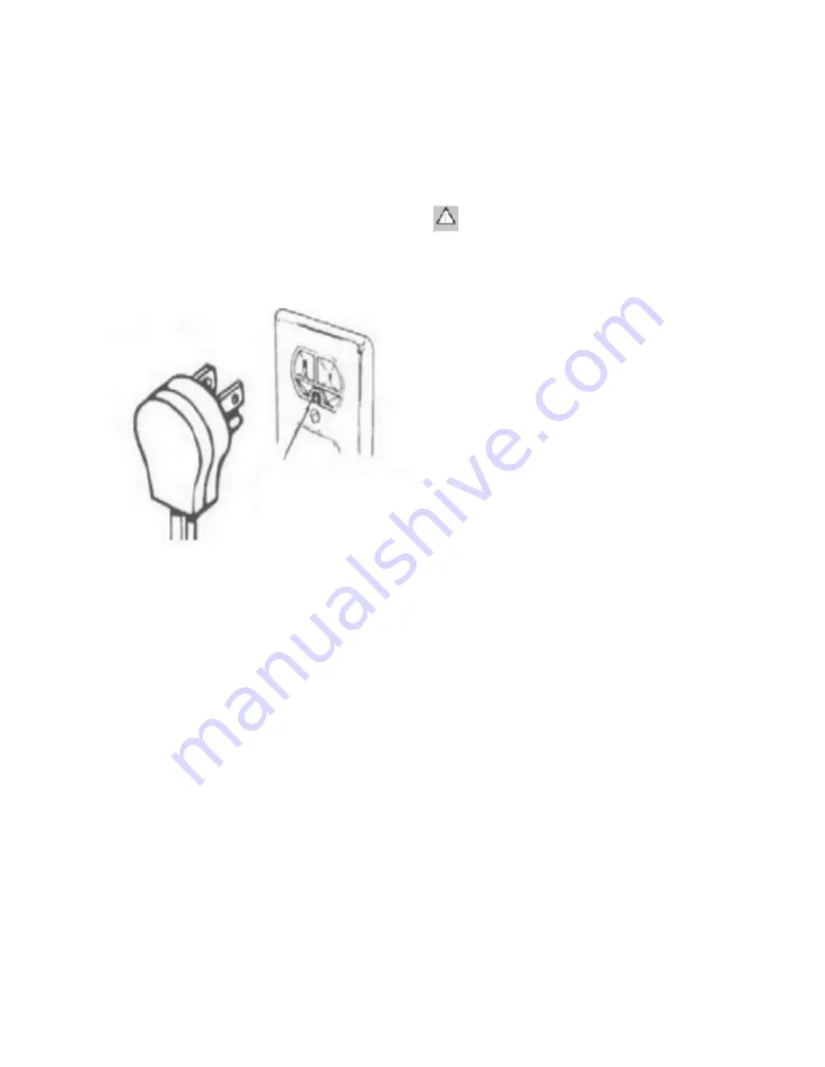
1 The range is equipped with a three-prong power
cord (grounding plug which mates with a
standard three-prong grounding wall receptacle
to minimize the possibility of electrical shock
hazard from the range).
2 Where a standard two-prong wall receptacle is
encountered, it is the responsibility and
obligation of the customer to have it replaced
with a properly grounded three-prong wall
receptacle. Do not cut or remove the grounding
prong from the power cord.
CONNECT RANGE TO GAS SUPPLy
1
Turn off gas.
2
Install a male 1/2” flare union adapter to 1/2” NPT
internal thread of regulator inlet.
3
Connect flexible gas line connector to end union
and regulator inlet.
4
Install the male flare union adapter on the manual
shut-off valve, taking care to support the shut-off
valve . Do not allow the valve to move or turn.
5
Position the range into the cabinet to allow
connection of flexible connector at the shut-off
valve.
6
When all connections have been made, make sure
all range controls are in th “OFF” position and turn
on main gas supply valve.
7
Use a leak detector at all joints and connections to
check for leaks in the system. Do not use a flame
to check for gas leaks.
Ensure proper grounding
exists before use
The appliance must be isolated from the building’s gas
supply piping system by closing it’s individual manual
shut-off valve during any pressure testing of the gas
supply piping system at test pressures equal to or less
than 1/2 psig (3.5kPa).
CONNECT RANGE TO GAS SUPPLy
wARNING
• Do not apply excessive pressure when tightening
gas connections and fittings.
• Do not use teflon tape or plumber’s putty on gas
flex line connections.
• Turn all control valves to the “OFF” position. Turn
on gas supply and check all lines and
connections with leak detector, such as soap and
water solution. Do not use flame to check for leaks.
After verifying that there are no gas leaks, turn off
the gas supply to the range by turning the gas
shut-off valve to the “OFF” position.
• For LP installations, the LP gas tank must have its
own high pressure regulator. This is in addition to
the pressure regulator provided with the range.
• The maximum gas supply pressure to the
regulator must never exceed 1/2 pound per square
inch.
INSTALLING THE RANGE
Measure from the floor to the countertop and adjust the
leveling legs as required to position the top frame at the
desired height, based on the cabinet and countertop
installation. Carefully slide the range into position in
the cutout.
Make sure the anti-tip bracket is installed as
directed
1. Slide range forward.
2. Make sure the anti-tip bracket is securely
attached to the wall behind the range.
3. Safely slide the range slightly and move back
against wall, making sure the pin slides under
bracket.
Installing the burner components
Remove the burner bases, burner heads, burner caps,


