Installation Information
2-4
Electrical Information
These guidelines must be followed to ensure that safety
mechanisms in the design of the unit will operate
properly.
Refer to the serial plate for correct electrical rating. The
power cord of the unit is equipped with at three-prong
grounding plug for protection against shock hazards. It
must be plugged directly in to its own properly grounded
three-prong receptacle, protected with a 15 amp time
delay fuse or circuit breaker. The receptacle must be
installed in accordance with the current edition of the
National Electrical Code (NFPA 70) the local codes and
ordinances. Consult a qualifi ed electrician. Receptacles
with Ground Fault Circuit Interrupters (GFCI) are NOT
RECOMMENDED. DO NOT USE AN EXTENSION
CORD OR AN ADAPTER PLUG.
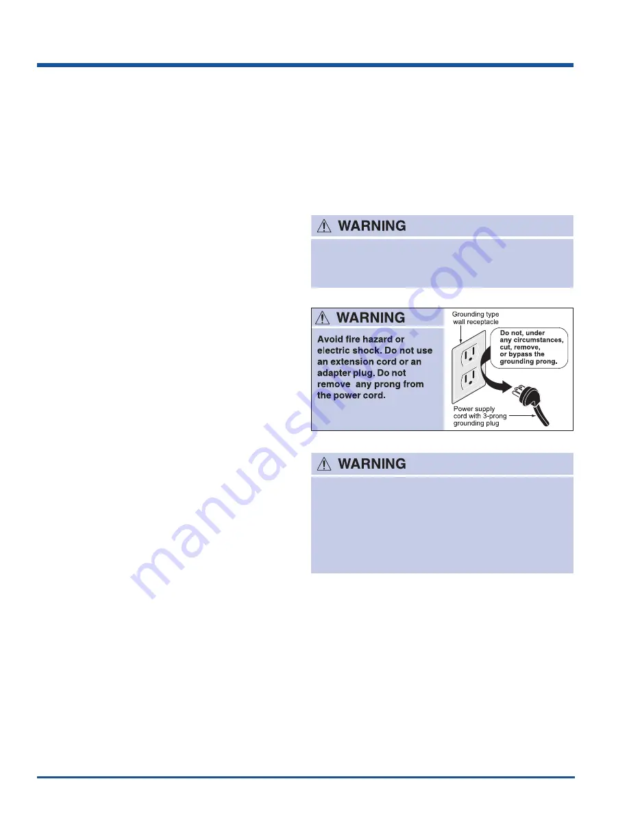
Figure 2-3. Electrical Receptacle
Avoid fire hazard or electric shock. Do not use an
extension cord or an adapter plug. Do not remove
any prong from the power cord.
Never unplug the freezer by pulling on the power
cord. Always grip the plug firmly and pull straight
out from the receptacle.
Turning the control to “OFF” turns off the
compressor but does not disconnect power to
other electrical components.
Leveling Instructions For All
Refrigerator/Freezer Pairs
• Remove two leg levelers provided in literature bag.
While unit is lying on its back for wood skid removal,
install both leg levelers in rear of unit.
• Level door of first unit using all four levelers and
slide unit into place. Recheck for levelness and
adjust if necessary.
• Measure distance from floor to bottom of door on
first unit. Adjust and level second unit so door height
matches.
• Leg Level Adjustments:
• One full turn of all four leg levelers will raise door
5/32”.
• One full turn of both front leg levelers will raise door
3/16” and tilt top of door back 7/16”.
• One full turn of both rear leg levelers will lower door
1/32” and tilt top of door forward 7/16”.
• One full turn of both side leg levelers will raise door
3/16” and tilt top of door 3/8”.
• Slide second unit into place leaving a minimum gap
of 3/16” between units for door swing clearance.
• This last step may require at least one extraction of
the second unit to properly align units in a “built-in”
application.
If the voltage varies by 10% or more, freezer and/or
refrigerator performance may be affected. Operating any
unit with insuffi cient power can damage the motor. Such
damage is not covered under the warranty. If you suspect
your voltage is high or low, consult your power company
for testing.
To prevent the freezer from being turned off accidentally,
do not plug the unit in to an outlet controlled by a wall
switch or pull cord. Do not pinch, knot, or bend the power
cord in any manner.
Summary of Contents for E32AR75FPS
Page 2: ......
Page 10: ...1 8 Basic Information All Freezer Specifications ...
Page 12: ...1 10 Basic Information Notes ...
Page 24: ...Installation Information 2 12 Figure 2 21 Figure 2 22 ...
Page 25: ...Installation Information 2 13 Figure 2 23 Figure 2 24 ...
Page 28: ...Installation Information 2 16 Notes ...
Page 43: ...Ice Maker 4 13 ...
Page 44: ...Ice Maker 4 14 ...
Page 62: ...Sealed System 5 18 HFC 134a CFC 12 Pressure Temperature Chart ...
Page 90: ...Component Teardown 6 26 Notes ...
Page 92: ...Parts List 7 2 All Freezer Pro Cabinet Exploded View Model E32AF75FPS ...
Page 94: ...Parts List 7 4 All Freezer Pro System Exploded View Model E32AF75FPS ...
Page 96: ...Parts List 7 6 Ice Maker Exploded View Model E32AF75FPS ...
Page 98: ...Parts List 7 8 All Refrigerator Pro Door Exploded View Model E32AR75FPS ...
Page 100: ...Parts List 7 10 All Refrigerator Pro Cabinet Exploded View Model E32AR75FPS ...
Page 102: ...Parts List 7 12 All Refrigerator Pro System Exploded View Model E32AR75FPS ...
Page 104: ...Parts List 7 14 Notes ...
Page 108: ...Troubleshooting 8 4 Notes ...
Page 109: ...9 1 Wiring Schematics Ice Maker Schematic ...
Page 110: ...Wiring Schematics 9 2 All Freezer Pro Wiring Diagram ...
Page 111: ...Wiring Schematics 9 3 All Refrigerator Pro Wiring Diagram ...
Page 112: ...Wiring Schematics 9 4 Notes ...


