Component Teardown
6-23
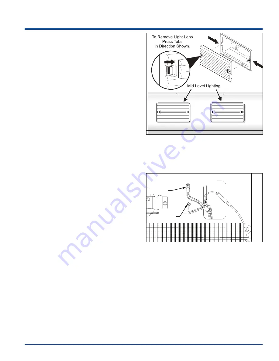
Mid Level Lighting Removal
The mid level lighting components may be accessed
without the evaporator cover being completely removed
from the compartment. By pulling the top of evaporator
cover away from the rear wall, the light wire harness
connections and light fi xture may be accessed.
To remove the mid level lighting on the evaporator cover:
1. Disconnect power from unit.
2. Remove the lens from the lamp housing by
unsnapping it from the lamp housing using your
fingers or a screwdriver. Be careful not to break the
locking tabs on the lamp housing. (See Figure 6-51)
3. Remove bulb by turning counterclockwise.
4. Remove evaporator cover or remove screws and pull
away top of cover enough to access components
mounted to rear of cover, then disconnect the wire
leads from the light fixture terminals.
5. Remove light fixture by pressing in the retaining
latches and pushing the light fixture through the
evaporator cover.
Thermistor Removal
The evaporator cover does not need to be completely
removed to access the thermistor wire harness
connections and mounting screw, however, removing the
evaporator cover from the unit will make the task easier.
To remove the thermostat control:
1. Disconnect power from unit.
2. Remove the adjustable shelves.
3. Remove the freezer drawers and supports.
4. Remove the evaporator cover screws, then pull the
top of the evaporator cover away from the back wall
enough to access the thermistor mounting screw and
electrical connection.
5. Extract the screw securing the thermistor to the back
wall of the cabinet interior. (See Figure 6-52)
6. Disconnect thermistor from wire harness at the quick
disconnect. Thermistor is now free.
Figure 6-52. Thermistor Removal
NOTE:
The lighting wire harness is not shown for clarity.
Thermistor
Screw
Electrical
Connection
Ground
Wire
Figure 6-51. Mid Level Lighting Removal
Summary of Contents for E32AR75FPS
Page 2: ......
Page 10: ...1 8 Basic Information All Freezer Specifications ...
Page 12: ...1 10 Basic Information Notes ...
Page 24: ...Installation Information 2 12 Figure 2 21 Figure 2 22 ...
Page 25: ...Installation Information 2 13 Figure 2 23 Figure 2 24 ...
Page 28: ...Installation Information 2 16 Notes ...
Page 43: ...Ice Maker 4 13 ...
Page 44: ...Ice Maker 4 14 ...
Page 62: ...Sealed System 5 18 HFC 134a CFC 12 Pressure Temperature Chart ...
Page 90: ...Component Teardown 6 26 Notes ...
Page 92: ...Parts List 7 2 All Freezer Pro Cabinet Exploded View Model E32AF75FPS ...
Page 94: ...Parts List 7 4 All Freezer Pro System Exploded View Model E32AF75FPS ...
Page 96: ...Parts List 7 6 Ice Maker Exploded View Model E32AF75FPS ...
Page 98: ...Parts List 7 8 All Refrigerator Pro Door Exploded View Model E32AR75FPS ...
Page 100: ...Parts List 7 10 All Refrigerator Pro Cabinet Exploded View Model E32AR75FPS ...
Page 102: ...Parts List 7 12 All Refrigerator Pro System Exploded View Model E32AR75FPS ...
Page 104: ...Parts List 7 14 Notes ...
Page 108: ...Troubleshooting 8 4 Notes ...
Page 109: ...9 1 Wiring Schematics Ice Maker Schematic ...
Page 110: ...Wiring Schematics 9 2 All Freezer Pro Wiring Diagram ...
Page 111: ...Wiring Schematics 9 3 All Refrigerator Pro Wiring Diagram ...
Page 112: ...Wiring Schematics 9 4 Notes ...


