background image

Summary of Contents for E42BS75ETT - 42" - Refrigerator

Page 1: ...ainless Steel Handles 34 Water Line 29 Water Supply 35 Troubleshooting Tips 38 40 Normal Operating Sotnlds 37 Consumer Support Consumer Support Back Cover Performance Data Sheet 43 State of California Water Treatment Device Certificate 44 Warranty Canadian 41 Warranty U S 42 Write the model and serial numbers here Model Serial Find these numbers on a label inside tile refl igerator coinpartinent a...

Page 2: ...stick to these extreinely cold surfaces Do not store or use gasoline or other fleaninable vapors ea_d licit Ms in the vicinity of this or may other appliealce In refligerators with autoinatic iceinakei3 avoid contact with the moving pea ts of the ejector inechanism or with the heating element located on the bottoin of the iceinaker Do not place fingers or hgulds on the autoinatic icemaking mechall...

Page 3: ...ld refl igerator please follow the instructions below to help prevent accidents Before You Throw Away Your Old Refrigerator or Freezer Refrigerants All refrigeration products contain refrigerants which under federal law must be removed prior to product disposal If you are getting rid of an old refl igeration product check with the company handling the disposal about what to do Take off the doors L...

Page 4: ...erator should always be plugged into its own hldividual electrical outlet which has a voltage rating that matches the rating plate This provides tile best performance guld also prevents overloading house wiring circuits which could cause a fire hazard fl oin overheated wires Never unplug your refl igerator by pullhlg on tile power cord Alwaysgrip plug fh mly and pull straight out fl om the outlet ...

Page 5: ... the down al row for colder temperatures until the desh ed temperature is displayed Refl igerator teinperatures call be adjusted between 34 F and 46 F alld the fl eezer teinperatures call be adjusted between 6 F alld 6 F Once tile desh ed teinperature has been set the temperature display will clear after 60 seconds To display the teinperature the Disp romp button inay be tapped Several adjustinent...

Page 6: ...o filter for approximately 6 months under normal household usage O If you are replacing the cartridge first remove the old one by depressing the ejection button O Insert the new filter with approximately 1 lb of force so that the filter is coinpletely seated NOTE If the filter is not seated properly water inay leak fl oin the filtration systein or no water will be dispensed O Run water fl om the d...

Page 7: ...nugger helps prevent tipph_g spillh_g or slidh_g of sinall iteins stored on the door shelf Place a fh_ger on either side of the snugger near the rear and inove it back and forth to fit your needs Donot block Top freezer bin CAUTION Make sure that items do not btockor fall into theicechute Spillproof Shelves and Freezer Shelves The special edges are designed to help prevent spills fl om dripping to...

Page 8: ...l at the stop position will be reduced as the door is loaded with food When the door is at 90 open it will automatically close Beyond this step the door wilt stay open 1 Door Alignment If doors ewe uneven adjust the refrigerator dooI Usln a 0 g 7 32 socket wrench turnthe door adjusting screw clockwise to raise the dooi counterclockwise to lower the door A on plug imbedded in the tl_ eads of the pi...

Page 9: ...fresh food drawers Toreplace fresh fooddrawers O Pull the desired drawer out to the O Tip the back rollers of the drawer stop position behhld the rollers in the track O Lift up slightly on the front of the drawer Lower the front of the drawer into normal position Pull the drawer slightly forward and out of the refl igerator Slide the drawer to the back of the refl igeratoi Toremove freezer baskets...

Page 10: ...cted Cubed Ice This hal pens occasionally when a few cubes accidentally get dit ected to the cI usheI After crushed ice is dispensed soine water inay drip fl oin the chute The first glass of water dispensed may be wariner than the following ones This is norinal 10 Automatic Icemaker A newly installed refrigerator may take 12 24 hours tobegin making ice Tile iceinaker will produce seven cubes per r...

Page 11: ...ll the water system Toflush out impurities in the water line throw away the first six glassfuls of water k CAUTION Neverputfingers or any other objects into the ice crusher discharge opening Locking the Dispenser Press the LOCK LIGHT button for 3 seconds to lock the dispenser eald control pealel To unlock press and hold the button again for 3 seconds To tun_ the Door Alea in on press the DOOR R AR...

Page 12: ...ing bleach because these products coal scratch and dainage tile fintsh Stainless steel Regulea ly cleeal and polish the Stainless Steel Dooi_ with a cominercially available stainless steel clegulei Do not use appliance wax oi polish on the stainless steel Cleaning the Inside Turnoff power at the circuit breaker or fuse box before cleaning If tilts is not practical wI ing excess moisture out of spo...

Page 13: ...ator If tile teinperature can drop below fl eezing have a qualified servicer drain tile water supply system to prevent serious property deanage due to flooding Preparing to Move Secure all loose items such as shelves ealct drawers by taping them securely in place to prevent damage CAUTION Due to the weight andsizeofthisrefrigerator andtoreducethe riskofpersonalinjuryordamagetothe produc_ A MINIMUM...

Page 14: ...sure until the shield snaps hi place Set the master power switch to the on position and close the grille panel Freezer Compartment Raise the grille pgu_el set the master power switch to the 0 off position eald allow lamps to cool Remove the iteins fl oin the shelf just below the light sh ld Reinove the shelf To remove the light shield press clown on the top of the shield and pull the tabs out of t...

Page 15: ... Time 90 minutes new installations require more time than replacement installations 2 CAUTION Due to the weight and size of this refrigerator and to reduce the risk of personal injury or damage to the product A MINIMUM OF 4 PEOPLE ARE REQUIRED TO BRING THE UNIT INTO THE HOME AND 2 PEOPLE ARE REQUIRED FOR PROPER INSTALLATION WARNING These refrigerators are top heavy and must be secured to prevent t...

Page 16: ...for 1 4 side panels if installing side panels 3B Wood Block Water Shutoff Valve 1 4 0 D Copper Water Line Tubing 12or 14 WoodScrews Screws Special 3M Dual Lock Adhesive Strips Custom Panels TOOLS REQUIRED Tinsnips to cut banding Stepladder Bucket Level Appliance dolly Tubing cutter Flathead screwdriver 1 2 open end wrench 2 Phillips screwdriver Drill and appropriate bits 7 32 1 2 sockets Safety gl...

Page 17: ...ater connection location The line should be long enough to extend to the front of the refrigerator Installation of an easily accessible shutoff valve in the water line is required DIMENSIONS AND CLEARANCES 25 3 8 Case Depth 81 3 at Re_ Shipping height The front height maybe adjusted from 83 1 2 to 84 1 2 byadjusting front and rear leveling legs a maximumof 1 Depth Including Handles 26 7 8 Product ...

Page 18: ...tallation Instructions Refrigerator r23_7 8 From i i Rearof z_ E_ Refrigerat r Case lr m 1 2 1 4 3 4 Custom Panel NominalSize Fresh Food Door BackerPane Top View 130 Door Swing factory setting Scale 1 1 18 ...

Page 19: ...Installation Instructions Refrigerator Top View 90 Door Swing optional setting Scale 1 1 Fresh Food Door CaseTrim 23 7 8 FromRearof Refrkerator I I I 19 ...

Page 20: ...custom panel options You can install a 1 4 framed panel a 3 4 framed custom panel or a 3 4 full width overlay custom panel 1 4 Framed Panels You may install 114 thick custom panels from your cabinet manufacturer The decorative panel slides into the factory installed trim DoorHandles 3 4 Full Width Overlay Custom Panels 3 4 full width overlay custom panels are designed to slide into the factory ins...

Page 21: ...nels A GrillePanel m m T F Dispenser Cutout c J Freezer Fresh Food Panel Panel _ 1 I 1_ I el Front Panel Dimensions in inches 42 Models 39 15 16 10 3 4 67 7 8 16 7 16 22 11 32 17 13 16 35 5 32 IMPORTANT NOTE Dispenser Trim The refrigerator is supplied with factory installed dispenser trim If panel is less than 1 4 thick a noticeable gap will be created around the dispenser trim Foam tape may be ap...

Page 22: ...right offset is not equal to top to bottom offset 3 4 FULL WIDTH OVERLAY CUSTOM PANEL OPTION This design provides a nearly trimless appearance The full width overlay panel covers most of the door trim In this design a spacer panel must be installed between the finished backer and overlay panel OverlayPanel Cust I Overlay _ Door Pane_ J 7 1_4 Backer t 10 Inch Panel Spacer i i NOTE Left to right off...

Page 23: ...o a 1 4 finished backer panel This design provides a framed appearance Fresh Food Panel 1 Required for Optimal Handle Qearance 3 1 8 1 ThickMax or 3 4 Plus 1 4 Backer 3 8 1 4 Max T 3q 8 Min _ 1 4 Backer Panel 22 5 16 67 7 8 3 4 Overlay Panel 18 13 16 67 1 4 5 16 A 23 ...

Page 24: ...15 16 10 3 4 5 1B _ 3 4 Overlay Panel 39 7 16 10 1 8 Upper Freezer Panel 5 16 _ 1 Thick Max I or 3 4 Plus 1 4 Backer 3 1 8 3 8 Required for Optimal Handle Clearance 1 4 Backer Panel 16 7 16 17 13 16 3 4 Overlay Panel 12 15 16 17 3 16 T 1 4 Max Lower Freezer Panel _Fd 2_L _ r 1 I 1 4 Backer Panel 16 7 16 35 1 8 3 4 Overlay Panel 12 15 16 34 1 2 A _ _Thic k Max r or3 4 Plus 3 1 8 1 4 Backer 3 8 24 ...

Page 25: ...de Allow 3 5 8 on the handle side Secure the panels with glue Be sure to observe clearances shown on all sides Secure the overlay panel to the assembled backer spacer panel Use glue and screws Countersink screws into the backer panel Finished Backer Panel 3 5 8 1 2 Panel Required for Optimal Handle Clearance 1 4 _1_31 8 Min_ Max 3 1 8 _ _1 2 114 Backer Panel 22 5116 67 718 0 10 Spacer Panel 18 3 1...

Page 26: ...ecure the appearance panel to the assembled backer spacer panel Use glue and screws Countersink screws into the backer panel Grille Panel _la 2_L _ r 1 I 114 Backer Panel 39 15 16 10 314 0 10 Spacer Panel 38 15116 9 3 4 3 4 Overlay Panel 40 3 16 11 3q 8 Required for Optimal Handle Clearance Upper Freezer Panel _la _r_ _ r 1 I 1 4 Backer Panel 16 7 16 17 13 16 0 10 Spacer Panel 12 5 16 16 3 8 3 4 O...

Page 27: ...u are working GROUNDING THE REFRIGERATOR IMPORTANTiplease read carefully FOR PERSONAL SAFETY THIS APPLIANCE MUST BE PROPERLY GROUNDED The power supply cord of this appliance is equipped with a three prong grounding plug which mates with a standard three prong grounding wall receptacle to minimize the possibility of electric shock hazard from this appliance Have the wall outlet and circuit checked ...

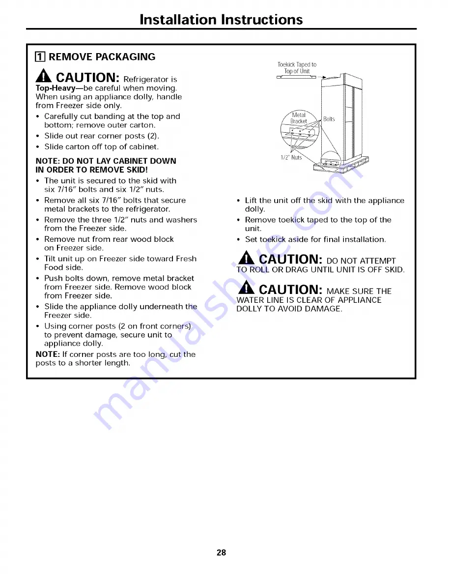
Page 28: ...Freezer side Remove nut from rear wood block on Freezer side Tilt unit up on Freezer side toward Fresh Food side Push bolts down remove metal bracket from Freezer side Remove wood block from Freezer side Slide the appliance dolly underneath the Freezer side Using corner posts 2 on front corners to prevent damage secure unit to appliance dolly NOTE If corner posts are too long cut the posts to a sh...

Page 29: ...rizontal water pipe make the connection at the top or side to avoid drawing off any sediment from the water pipe Drill a 1 4 hole in the water pipe Fasten the shutoff valve to the pipe with pipe clamp Tighten the clamp screws until the sealing washer begins to swell Do not OVERTIGHTEN Place a compression nut and ferrule sleeve for copper tubing onto the end of the tubing and connect it to the shut...

Page 30: ...ll studs ALTERNATE ANTI TIP PRECAUTIONS SKIP THIS STEP WHEN USING ANTI TIP BRACKETS All Profile built in refrigerators are Top Heavy They must be secured to prevent the possibility of tipping forward Use this alternative method to secure the refrigerator whenever steel wall studs are encountered TopCaseTrim i i i i i i SideView Install 4 1 1 2 DrywallScrews Through TrimandInt0Soffit or3 4 Min Wood...

Page 31: ... are accessible from the front of the refrigerator To level the back of the refrigerator turn the 1 2 hex nut located above the front wheels Turn clockwise to raise or counterclockwise to lower the refrigerator For front leveling use a 7 16 open end wrench Adjust height of refrigerator to match installation cutout opening 83 1 2 to 84 1 2 The refrigerator should be level and plumb with cabinets l ...

Page 32: ...G IS SATISFACTORY FOR YOUR INSTALLATION SITUATION Open the door to view the bottom hinge Note the door stop pin location The pin is factory installed in the 130 position Partially close the door From above use a flat head screwdriver to unscrew the door stop pin and reinstall into the 90 position Interior J l I if f I_ y r d _J Hinge INSTALL GRILLE PANEL Raise the grille panel to the stop position...

Page 33: ...el in until it slides into the slot behind the trim Gently push to opposite side Repeat procedure for upper and lower Freezer panels Reinstall Handles Reinstall Fresh Food door handle with the original 5 Phillips head screws Tighten Repeat for Freezer door handle NOTE Ensure that the edge of the handle does not pinch the door gasket 3 4 Custom Decorative Panels If you choose to install custom wood...

Page 34: ... most allen set screw B with supplied allen wrench then fasten bottom allen set screw C See Figure 1 4 Repeat Step 3 with bottom end cap using allen set screws D and E once upper section of handle is firmly secured to door See Figure 2 5 All set screws should be tightened and sub flush allen set screw should be buried just below the surface of the end cap of handle end cap The end caps should be d...

Page 35: ...the union fitting on the unit and tighten nut to union Turn on the water to check for leaks Note Make sure excess tubing length does not interfere with toekick installation TURN ON THE POWER Set the Master Power switch to the I ON position Check to make sure power to refrigerator is on by opening refrigerator door to see if interior lights are on Master Powerswtch The temperature controls are pres...

Page 36: ...d for proper air flow DOOR ALIGNMENT Stand back from the refrigerator to inspect the door alignment Shipping or the addition of heavy door panels may have caused the doors to move slightly out of alignment Raise Clockwise If necessary the Fresh Food door may be adjusted up or down to align with the Freezer door Loosen the leveling mechanism Use a 7 32 wrench to adjust the hinge pin as shown Tighte...

Page 37: ...ts Expansion and contraction of cooling coils during and after defl ost can cause a cracking or popping sound After an icemaking cycle you may hear the ice cubes dropping into the ice bucket WHIRl You inay hear the fans spinning at high speeds This happens when the refl igerator is first plugged in when the doors are opened fl equently or when a large amount of food is added to the refl igerator o...

Page 38: ...ten Hot weather or frequent This is normal to maintain even door openings temperatures Temperature controls SeeAbout the temperaturecontrols set at tire coldest setting Refrigerator orfreezer Temperature control not set See About the temperaturecontrols compartment too warm cold enougb Warm weather or frequent Set the teini erature control one step colder door openings See About the temperature co...

Page 39: ...he LOCKbutton fbr 3 seconds Waterhaspoor taste _or Water dispenser has not been Dispense water until all water in system is replenished used for a long time Waterinfitstglass is warm Normal when refrigerator Wait 24 hours for the refi igerator to completely cool down is first installed Water dispenser has not been Dispense water until all water in system is replenished used for a long time Water s...

Page 40: ...ries moisture into refrigerator when doors are opened Interiorlight does No power at nuclei Replace fuse or reset the breaker net work Light bulb burned out See Replacing the light bulbs Water on kitchen floor or Cubes jammed in chute Poke ice through with a woodell Sl OOll on bottomof freezer Hot air from top Normal air flow cooling motor of refrigerator In the refrigeration process it is normal ...

Page 41: ...nts repaired or replaced are warranted through the remainder of the original warranty period only This warranty is in addition to any statutory warranty WHAT IS NOT COVERED Owner is responsible to pay for service calls related to product installation and or teaching how to use the product Damage to finish must be reported within 48 hours following the delivery of the appliance Service trips to you...

Page 42: ...th instructions provided with the appliance and in accordance with all local plumbing electrical and or gas codes 3 Proper connection to a grounded power supply of sufficient voltage replacement of blown fuses repair of loose connections or defects inhouse wiring 4 Expenses for making the appliance accessible for servicing such as removal of trim cupboards shelves etc which are not a part of the a...

Page 43: ...nk Polyethylene Plastic Tubing Polyethylene Plastic Filter Media Extruded Carbon block REPLACEMENT CARTRIDGE INFORMATION I Replacement cartridges are available through your local Electrolux dealer or the Customer Care Center at 1 877 435 3287 Please reference installation instructions in the Use Care Guide for replacing the cartridge and warranty information Estimated cost for I the replacement fi...

Page 44: ...s listed on this certificate hax e met the testing requirements pursuant to Section 116830 of the Health and Safety Code for the fotlm_ ing health related contalninants Microbiological Contaminants and Turbidit5 Cysts protozoam Turbidity Inor_anic Radiolo_lcal Contaminants Organic Comaminants Alachlor Atrazine Lindane 2 4 D Toxaphene Rated Service Capacity 400 gallons Rated Service Flow 0 5 gpm Do...

Reviews: