13
30” FULL GAS RANGE INSTALLATION INSTRUCTIONS
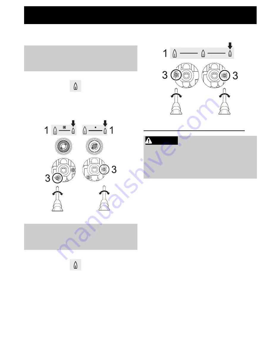
Adjusting the minimum gas setting
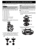
Circular Dual Flame burners
1. Push in the burner control knob and light it at the
minimum position
.
2. Remove the burner control knob, along with the
conical spring and knob ring.
3. Tighten or loosen the highlighted screws to adjust
the minimum flame height.
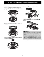
Circular Single Flame burners and Fish burner
1. Push in the burner control knob and light it at the
minimum position
.
2. Remove the burner control knob, along with the
conical spring and knob ring.
3. Tighten or loosen the highlighted screws to adjust
the minimum flame height.
Conversion to Propane gas (LPG)
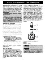
Always provide an adequate gas supply.
This appliance is shipped from the factory for use
with natural gas. Use this kit to convert the appli-
ance for use with propane gas, if necessary. Comply
with the following: Ensure that the range is con-
verted for use with the appropriate gas before using
it.
This appliance is designed to operate at a pressure
of 10" of water column when used with propane gas.
When checking if the regulator is working properly,
the inlet pressure must be at least 1" greater than
the operating (manifold) pressure above.
When converting for propane gas use, the pressure
supplied to the regulator must be between 11" and
13" of the water column. The pressure regulator
located in the inlet of the range manifold must
remain in the supply line. Use a flexible metal appli-
ance connector or rigid pipe to connect the range to
the gas supply. The connector should have an inside
diameter of 1/2” and be 5 ft (1.5 m) or less in length.
(Exception: Maximum connector length in Massa-
chusetts installations is 3 ft (0.9 m). In Canada, the
connector must be single-wall metal and not longer
than 6 ft (1.8 m).
NOTE:
The Circular Dual flame burners are fitted
with two minimum adjustment screws. They are
slotted head and brass coated located at both
sides of the knob insertion rod.
NOTE:
The Circular Single Flame burners and
Fish burners are fitted with one minimum adjust-
ment screw. It is slotted head brass coated and is
located to the right or left of the knob insertion rod.
WARNING
• Before proceeding with the gas conversion, the
gas supply must be turned off before disconnect-
ing the electrical power.
• A gas leak test should be performed after the gas
conversion has been carried out.
Summary of Contents for ECFG3068AS
Page 63: ...914780107 A 432021 ...


