background image

1 0

Instructions for the Installer

Engineers technical data

Heating elements Ratings

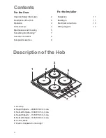
Rapid front left Hotplate Ø 180 mm

2090 W

Normal back left Hotplate Ø 145 mm

1040 W

Rapid front right Hotplate Ø 145 mm

1570 W

Normal back right Hotplate Ø 180 mm

1570 W

Total rating

6270 W

Cut out dimensions

Width:

550 mm

Depth:

470 mm

Thickness:

30 mm

Important safety requirements

This hob must be installed in accordance with the IEE
Wiring Regulations (Current Edition).
Detailed recommendations are contained in the following
British Standards Codes Of Practice: B.S. 6172/ B.S.
5440, Par. 2 and B.S. 6891 Current Editions.

Location

This hob has been registered as a "Class X" appliance
according to Fire Risk Regulations. Minimum distances
detailed below must be observed. The hob may be located
in a kitchen, a kitchen/diner or bed sitting room, but not
in a bathroom or shower room.
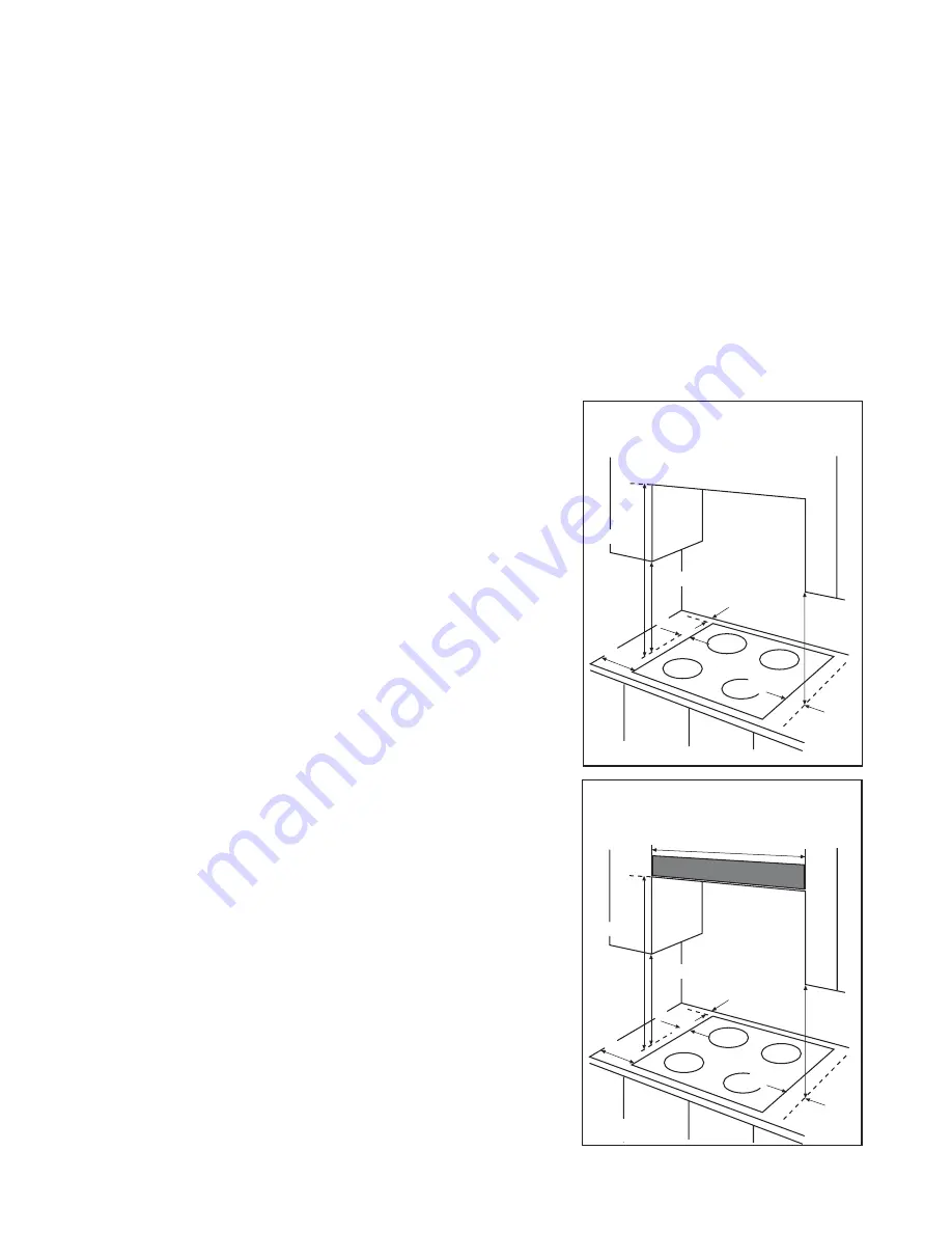
Before making the cut out in the worktop ensure that
there is a minimum distance of 55 mm between the rear
edge of the hob and the wall. A minimum distance of 100
mm. must be left between the side edges of the hob and
any adjacent cabinets or walls.
The minimum distance combustible material can be fitted
above the hob in line with the edges of the hob is 400
mm. If it is fitted below 400 mm a space of 50 mm must
be allowed from the edges of the hob.
The minimum distance combustible material can be fitted
directly above the hob is 700 mm.

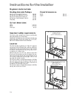
650 mm

400 mm

400 mm

100 mm

50 mm

50 mm

55 mm

600 mm

INSTALLATION GUIDANCE INSTRUCTIONS

CLEARANCES REQUIRED

WHEN FITTING THE HOB

WITH A COOKER HOOD ABOVE

FO 0813

700 mm

400 mm

100 mm

400 mm

50 mm

55 mm

50 mm

INSTALLATION GUIDANCE INSTRUCTIONS

CLEARANCES REQUIRED

 WHEN FITTING THE HOB

WITHOUT A COOKER HOOD ABOVE

FO 0812

Overall dimensions

Width:

580 mm

Depth:

500 mm

Summary of Contents for EEH

Page 1: ...INSTR INSTR INSTR INSTR INSTRUCTION BOOKLET UCTION BOOKLET UCTION BOOKLET UCTION BOOKLET UCTION BOOKLET P l e a s ere a d t h i s i n s t r u c t i o n b o o k l e t b e fo reu s i n gt h eap p l i a n c e 35674 9002 EEH ...

Page 2: ...2 ...

Page 3: ... in use z When using other electrical appliances ensure the cable does not come into contact with the hot surfaces of the hob z Unstable or misshapen pans should not be used on the hob as unstable pans can cause an accident by tipping or spillage z Never leave the hob unattended when cooking with oil and fats z Never use plastic or aluminium foil dishes on the hob z Perishable food plastic items a...

Page 4: ...an Guarantee 9 Contents 1 Hob Top 2 Rapid Hotplate 2090 W 180 mm dia 3 Normal Hotplate 1040 W 145 mm dia 4 Rapid Hotplate 1570 W 145 mm dia 5 Normal Hotplate 1570 W 180 mm dia 6 Control knobs 7 Electric Hotplates Control Light Description of the Hob 1 3 2 4 5 6 7 Installation 11 Building In 11 Electrical connections 13 Wiring diagram 14 For the User For the Installer ...

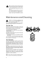
Page 5: ...F 1 Minimum 6 Maximum The hob has two types of hotplates Normal Hotplates We recommend the plates are switched to maximum 6 for a short while to boost the plate and then adjusted to the required setting Rapid Hotplates The rapid hotplates are indicated by a red dot and will heatupmorequicklythananormalplate Asthereddots arepaintedontheplate theymaydeteriorateduringuse andevendisappearcompletelyaft...

Page 6: ...plasticscourer To keeptheplateslookingasnew hotplateconditionercan bepurchasedfrommosthardwarestores e g 4Hob by HomeCareProducts followthemanufacturer sinstruction foruse Alternatively wipe the plates with a drop of olive oil on a kitchen towel to avoid rust It is important to note that the platewillsmokealittleandproduceaslightlyunpleasant odour when next used Stainless steel parts the stainless...

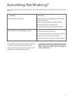
Page 7: ... the correct control knob has been turned Check the plate is clean and dry Check the cooking pan is the correct size for the plate Check the cooking pan has a flat bottom Check the setting is correct for the type of cooking If after all these checks your hob still does not operate correctly contact your local Service Force Centre Please note that it will be necessary to provide proof of purchase f...

Page 8: ...mercial environment plus those which are subject to rental agreements Products of Electrolux manufacturer that are not marketed by Electrolux Service and Spare Parts In the event of your appliance requiring service or if you wish to purchase spare parts please contact your local Service Force Centre by telephoning 0870 5 929 929 Your telephone call will be automatically routed to the Service Force...

Page 9: ...of the appliance The appliance guarantee is for the same period and to the same extent for labour and parts as exists in your new country of residence for this particular model or range of appliances The appliance guarantee is personal to the original purchaser of the appliance and cannot be transferred to another user The appliance is installed and used in accordance with instructions issued by E...

Page 10: ...kitchen a kitchen diner or bed sitting room but not in a bathroom or shower room Before making the cut out in the worktop ensure that there is a minimum distance of 55 mm between the rear edge of the hob and the wall Aminimum distance of 100 mm must be left between the side edges of the hob and any adjacent cabinets or walls The minimum distance combustible material can be fitted above the hob in ...

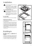
Page 11: ...N THE HOB IS FIRST INSTALLED Once the hob has been installed it is important to remove any protective materials which were put on in the factory The manufacturer will not accept liability should the above instructions or any of the other safety instructions incorporated in this book be ignored Cut Out Size The dimensions of the cut out are given in the diagram Supply Connections This hob is design...

Page 12: ...e kitchen unit b can be used for connections FO 0199 a Fitting the Hob into the worktop Carry out the building in of the hob as follows put the seals supplied with the hob on the edges of the cut out place them exactly on the front and rear edge and at 50 mm from the side edges taking care that the seals meet without overlapping place the hob in the cut out taking care that it is centred fix the h...

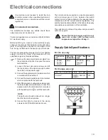
Page 13: ...he bottom of the hob A copy is attached on the back cover of this book The hob is supplied without supply cord A3 core flexible supply cord must be fitted in accordance with the specification given in the relevant tables 1 Remove the mains terminal cover plate from the underside of the hob to expose the mains terminal block 2 Loosen the two cable clamp screws and lift the top section of the clamp ...

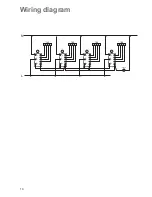
Page 14: ...14 Wiring diagram 4 3 2 1 4 3 1 2 5 P2 P 1 P3 1 4 3 2 1 4 3 1 2 5 P2 P 1 P3 2 4 3 2 1 4 3 1 2 5 P 2 P1 P 3 3 4 3 2 1 4 3 1 2 5 P2 P 1 P3 4 PLATE 145 180 145 180 N L ...

Page 15: ...15 ...

Page 16: ...Grafihe MDM Forlì 02 07 Customer Care Department Electrolux Major Appliances Addington Way Luton Bedfordshire LU4 9QQ Tel 08705 950 950 Electrolux plc 2003 ...

Reviews: