background image

39

Installation

Unpacking

Check that the cooker hood has no damages.
Transportation damages should immediately be
reported to the one responsible for the transport
Damages, faults and eventually missing details
should immediately be reported to the seller.
Take care of the packing material so that small
children cannot play with it.

Placement

The hood is to be mounted on the wall.
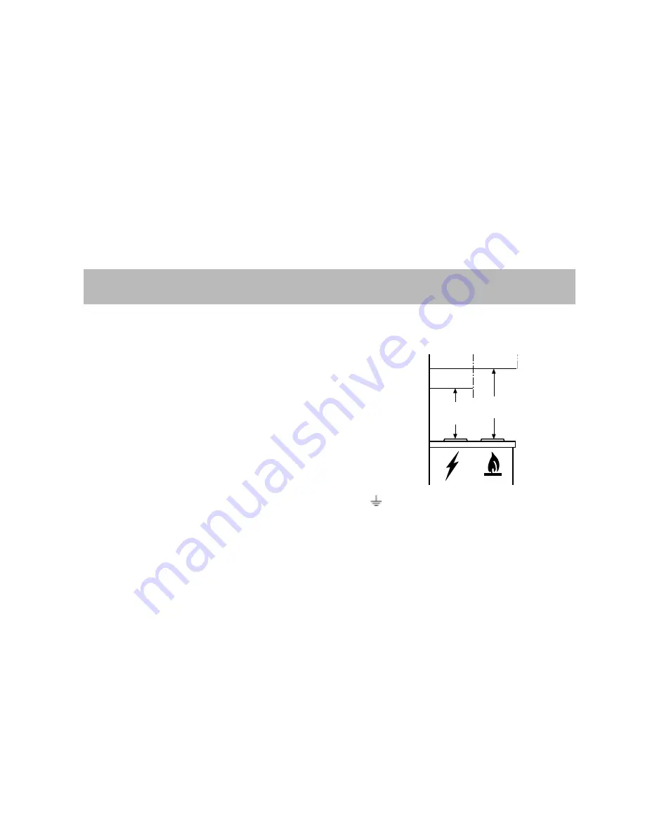
When installed, the hood must be not less than 50
cm. above electric burners or 65 cm. above gas or
mixed-fuel burners (Fig. 7).

Electrical connection (not for
UK)

Safety warnings for the electrician
Before connecting the appliance to the power
supply, check that the voltage indicated on the
rating plate corresponds to the mains power supply
available.  Appliances fitted with a plug can be
connected to any standard power socket within
easy access.
Should it be necessary to provide a fixed
connection, the hood must only be installed by an
electrician authorised by the local electricity board.
When installing, an omnipolar disconnector with a
distance of at least 3 mm between contacts must
be provided.
Fixed connection of the appliance must only be
carried out by an authorised electrician.

Electrical connection for UK
only

Safety warnings for the electrician
Connect the hood to the mains supply via a double
pole switch
which has 3 mm minimum separation between the
contacts.
The switch must be accessible at all times.
The following is valid in the United Kingdom only:
-

the wire which is coloured green and yellow
must be connected to the terminal which is
marked with the letter E or by the earth symbol

 ), or coloured green or green and yellow;

-

the wire which is coloured blue must be
connected to the terminal which is marked with
the letter N or coloured black, -

-

the wire which is coloured brown must be
connected to the terminal which is marked with
the letter L or coloured red.

Mounting accessories included

1 deflector
2 chimney supports
1 metal screw 3,5 x 6,5  (to affix the deflector to

the support)

1 support bracket
7 wood-screws 5 x 45 mm (for wall mounting)
7 wall plugs Ø 8 mm (for wall mounting)
2 metal screws 2,9 x 6,5 (for chimney flue

mounting)

6 metal screws 4 x 20 (to affix the screen to the

cooker hood)

1 allen spanner  (for TORX screws)

Min

65 cm

Min

50 cm

Fig. 7

Summary of Contents for EFC 9450

Page 1: ...Gebrauchsanweisung Notice d utilisation et d installation EFC 9450 F D Istruzioni di montaggio ed uso User manual UK I ...

Page 2: ...d keep it available at use of the cooker hood Safety warnings 33 For the installer 33 For the user 33 Description of the Appliance 34 Extractor version 34 Filter Version 34 Control Panel 35 Maintenance and care 36 Cleaning the hood 36 Metal grease filter 36 Removing the metal grease filter 36 Charcoal filter 37 Changing the light bulb 37 What to do if 38 Special accessories 38 Technical assistance...

Page 3: ...s used in its filtering function it will operate simply and safely in the above conditions without the need for any of the aforementioned measures When the hood is used in its extractor function the following rules must be followed to obtain optimal operation short and straight outlet hose keep bends in outlet hose to a minimum never install the hoses with an acute angle they must always follow a ...

Page 4: ...xtractor version In this version fumes are extracted to the outside via a hose connected to the coupling ring Fig 1 In order to obtain the best performance the hose should have a diameter equal to the outlet hole Fig 1 Filter Version The air is filtered through a charcoal filter and returned to the kitchen You will need an original ELECTROLUX charcoal filter for the filtering function See Special ...

Page 5: ... intensive speed the control ball lights up with a red flashing light depress again and hold depressed for about 3 seconds until a bip sound indicates the reset Switching on the hood Fig 3 The control ball is a balancer switch Depressing the control ball repeatedly towards the right switches on the hood and you may select the suction level desired depressing once again on the right the hood switch...

Page 6: ...grease filter The purpose of the grease filters is to absorb grease particles which form during cooking and it must always be used either in the external extraction or internal recycling function Attention the metal grease filters must be removed and washed either by hand or in the dishwasher every four weeks Removing the metal grease filter Pull the handles downards then extract the filter Fig 4 ...

Page 7: ... C After approximately three years of use the carbon filter should be replaced with a new as the odour reduction capacity will be reduced Fitting Remove the frame i which supports the filter h by turning 90 the two knobs g Insert the charcoal filter inside the frame and put all parts back in their place Fig 5 To remove proceed in the reverse order Always specify the hood model code number and seri...

Page 8: ...chase for any in guarantee service calls In guarantee customers should ensure that the above checks have been made as the engineer will make a charge if the fault is not a mechanical or electrical breakdown Special accessories Charcoal filter KF20 E Nr 942 120 600 Remote control RM 8700 942 120 658 Not available in UK please contact your local Service Force Centre Technical assistance service You ...

Page 9: ...ce of at least 3 mm between contacts must be provided Fixed connection of the appliance must only be carried out by an authorised electrician Electrical connection for UK only Safety warnings for the electrician Connect the hood to the mains supply via a double pole switch which has 3 mm minimum separation between the contacts The switch must be accessible at all times The following is valid in th...

Page 10: ...h a pencil dril the holes Ø8mm insert 2 wall plugs Fix the chimney support bracket to the wall using two 5x45mm screws 11 Hook the hood onto the bottom bracket 12 Fasten the hood to the wall with 1 5x45 mm screw ABSOLUTELY NECESSARY remount the carbon filter frame see also Fig 3 13 Connect a pipe pipe and pipe clamps not provided to be purchased separately for discharge of fumes to the connection ...

Page 11: ...41 15 16 18 19 20a 20b 20b H 16 Z G B 17 17 18b 15 OK 18a 18c 18d Fig 8 ...

Page 12: ... that proof of purchase is required for in guarantee service calls Help us to help you Please determine your type of enquiry before writing or telephoning When you contact us we need to know Your name Address and post code Telephone number Clear and concise details of the fault Name and model of the appliance E number This information can be found on the rating plate which can be seen when the gre...

Page 13: ...astic Costs incurred for calls to put right an appliance which is improperly installed or calls to appliances outside the European Community EC or European Free Trade Area Appliances found to be in use within a commercial environment plus those which are subject to rental agreements Products of Electrolux manufacture which are not marketed by Electrolux European Guarantee If you should move to ano...

Page 14: ...LI12AA Ed 11 02 ...

Reviews: