background image

7

Installation

Unpacking

Check that the cooker hood has no damages.
Transportation damages should immediately be
reported to the one responsible for the transport
Damages, faults and eventually missing details
should immediately be reported to the seller.
Take care of the packing material so that small
children cannot play with it.

Placement

The hood is to be mounted on the wall.
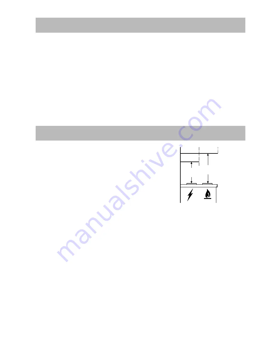
When installed, the hood must be not less than
50cm. above electric burners or 65 cm. above gas
or mixed-fuel burners (fig. 6).

Electrical connection

Before connecting the appliance to the power
supply, check that the voltage indicated on the
rating plate corresponds to the mains power supply
available.  Appliances fitted with a plug can be
connected to any standard power socket within
easy access.
Should it be necessary to provide a fixed
connection, the hood must only be installed by an
electrician authorised by the local electricity
board. When installing, an omnipolar disconnector
with a distance of at least 3mm between contacts
must be provided.
The manufacture declines all responsibility for
malfunctions resulting from failure to comply with
the above instructions.

Min

65 cm

Min

50 cm

Technical Specifications

Dimensions (in cm)

Height

72-114

Width

89,8

Depth

45

Maximum absorbed power

200 W

Motor absorption:

170 W

Lighting:

2 x 20 W

Lenght of the cable:

150 cm

We reserve the right to generate constructive and chromatic modifications as required by technological growth.

Special accessories

Charcoal filter  KL20

E-Nr. 942 120 600

Fig. 6

Electrical connection
220-240 V – by means of fixed power cable with
plug.
(Fixed connection of the appliance must only be
carried out by an authorised electrician.)

Summary of Contents for EFC 9461

Page 1: ...User manual EFC 9461 UK ...

Page 2: ...acking 7 Placement 7 Electrical connection 7 Mounting accessories included 8 Wall unit mounting 8 Before you use the cooker hood we recommend that you read through the whole user manual giving a direct description of the cooker hood and its functions To avoid the risks that are always present when you use a product driven by electricity it is important that the cooker hood is installed correctly a...

Page 3: ...office Since the rule for rooms with fuel burning appliances is outlet hole of the same size as the ventilation hole a hole of 500 600 cm2 which is to say a larger hole could reduce the performance of the extractor hood If the hood is used in its filtering function it will operate simply and safely in the above conditions without the need for any of the aforementioned measures When the hood is use...

Page 4: ...filter for the filtering function See Special Accessories Fix the deflector using 4 screws Ø3 5x9 5 mm Fig 2 Fig 1 D Fig 2 Light switch Extractor fan switch Push button 1 Push button 2 0 1 2 3 Push button 3 Best results are obtained by using a low speed for normal conditions and high speed when odours are more concentrated Turn the hood on a few minutes before you start cooking then you will get a...

Page 5: ...e metal grease filter First push the metal grease filter stop backwards then extract the filter pulling downwards Fig 3 Hand washing Soak grease filters for about one hour in hot water with a grease loosening cleaner then rinse off thoroughly with hot water Repeat the process if necessary Refit the grease filters when they are dry Dishwasher machine Place grease filters in dish washer Select most ...

Page 6: ... After approximately three years of use the charcoal filter should be replaced with a new as the odour reduction capacity will be reduced Mounting Remove the frame b which supports the filter c by turning 90 the two knobs a Fig 4 Insert the coal mattress inside the frame and put all parts back in their place d To dismount proceed in reverse order Always specify the hood model code number and seria...

Page 7: ...rd power socket within easy access Should it be necessary to provide a fixed connection the hood must only be installed by an electrician authorised by the local electricity board When installing an omnipolar disconnector with a distance of at least 3mm between contacts must be provided The manufacture declines all responsibility for malfunctions resulting from failure to comply with the above ins...

Page 8: ...f the template corresponds to the lower side of the hood once mounted 2 Drill two holes Ø 8mm and fix the support bracket with two wall plugs and screws 3 Hang the hood 4 and adjust its position 5 6 From the inside of the hood sign two points for definitive fixing 7 Remove the hood 8 and drill two holes Ø 8mm 9 fit two wall plugs 10 Drill two holes Ø 8mm on the upper side close to the ceilling fit...

Page 9: ...9 ...

Page 10: ...10 ...

Page 11: ...11 ...

Page 12: ...LI1Z3B Ed 10 02 ...

Reviews: