background image

22 electrolux 

INSTALLING THE COOKER HOOD

EN

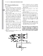
 Fitting the Wall Brackets

Wall marking:
• Draw a vertical line on the supporting 

wall up to the ceiling, or as high as 
practical, at the centre of the area in 
which the hood will be installed.

•  

Draw a horizontal line at 650 mm 
above the hob.

•  Place  bracket 

7.2.1 

on the wall as 

shown about 1-2 mm from the ceiling 
or upper limit aligning the centre with 
the vertical reference line (distance 
between the hole and the vertical line:
132,5 mm on both side of the line).

•  Mark the wall at the centres of the 

holes in the bracket.

•  Place  bracket 

7.2.1 

on the wall 

as shown at X mm below the 

fi

 rst 

bracket (X = height of the upper 
chimney section supplied), aligning 
the centre  with the vertical line 
(distance between the hole and the 
vertical line:132,5 mm on both side of 
the line).

•  Mark the wall at the centres of the 

holes in the bracket.

•  Mark a reference point as indicated 

at 116 mm from the vertical reference 
line and 306 mm above the horizontal 
reference line.

•  Repeat this operation on the other 

side.

•  Drill ø 8 mm holes at all the centre 

points marked.

•  Insert the wall plugs 

11 

in the holes.

•  Fix the lower bracket 

7.2.1 

using the 

12a 

screws (4,2 x 44,4) supplied.

•  Fix the upper bracket 

7.2.1 

(and, in 

case of hood installation in recycling  
version, the air outlet connection 

15

)  

using the 2 screws 

12a 

(4,2 x 44,4) 

supplied.

•  Insert the two screws 

12a 

(4,2 x 44,4) 

supplied in the hood body 

fi

 xing holes, 

leaving a gap of 5-6 mm between the 
wall and the head of the screw.

Note: If the hood is to be installed onto 
a hollow construction or plaster or 
partition board wall then special 

fi

 xing 

screws will be required (not supplied).

11

12a

306

X

116

1÷2

116

650 min.

7.2.1

132,5 132,5

15

Summary of Contents for EFC9062

Page 1: ...USER MANUAL EFC90620 ...

Page 2: ...We were thinking of you when we made this product ...

Page 3: ... will provide you with lots of pleasure in the future The Electrolux ambition is to offer a wide variety of quality products that make your life more comfortable You find some examples on the cover in this manual Please take a few minutes to study this manual so that you can take advantage of the benefits of your new machine We promise that it will provide a superior User Experience delivering Eas...

Page 4: ...self when the fan motor has cooled significantly It is dangerous to alter the specifications or modify this product in any way When installed between adjoining wall cabinets the wall cabinets must not overhang the hob If the room where the hood is to be used contains a fuel burning appliance such as a central heating boiler then its flue must be of the room sealed or balanced flue type If other ty...

Page 5: ...YOUR APPLIANCE electrolux 5 EN YOUR APPLIANCE ...

Page 6: ...off Touch control unlit Lights off When pressed for 2 seconds it starts the lighting system in courtesy light mode The lamps are fed at a reduced power of approximately 5W Such function can be stopped by pressing the touch control for 2 seconds or just by pressing it shortly in order to return to the normal lighting mode In courtesy light mode the touch control is not lit Touch control lit Lights ...

Page 7: ...ed Touch control lit T5 When pressed the motor is set to the intensive speed timed to 5 minutes At the end of 5 minutes of intensive speed the hood starts again at the speed it was set to previously In case the hood is set to the intensive speed directly from OFF state it will then start from the first speed after 5 minutes of intensive speed Touch control lit F When pressed for 4 seconds it reset...

Page 8: ...passing through the grease filters and is passed out through the ducting into the atmosphere To obtain the best performance when cooking it is advisable to switch the cooker hood on for a few minutes before you start cooking and leave it running for about 15 minutes after finishing When used in the ducting mode the charcoal filters are not required Never do flambé cooking under this cooker hood Ne...

Page 9: ...sive cleaners Never use excessive amounts of wa ter when cleaning particularly around the control panel Cleaning of the Suction panel Pull the suction panel to open it Slidethefixingpivotlevertodisconnect the panel from the hood casing Do not wash the panel in the dishwasher Clean the outside using a damp cloth and neutral liquid detergent Clean the inside as well using a damp cloth and neutral de...

Page 10: ...ood Pull the suction panel to open it Remove the metal grease filters one at a time by pushing them lateraly and simulta neously pulling downwards Any kind of bending of the filters has to be avoided when washing them Before fitting them again into the hood make sure that they are completely dry The colour of the filter surface may change throughout the time but this has no influence to the filter...

Page 11: ...e Mains or turning the Main switch off Restore the connection pressing and holding T2 Release the touch control touch controls L T2 and F will light up normally Within 3 seconds press the touch control F until the key itself flashes to confirm as follows 2 flashes Charcoal Filter saturation Alarm ENABLED 1 flash Charcoal Filter saturation Alarm DISABLED Reset the alarm signal Stop the motor Press ...

Page 12: ...pporting it with one hand Remove the halogen lamp from the lamp holder by pulling gently Replace the lamp with a new one of the same type making sure that you insert the two pins properly into the housings on the lamp holder Replace the snap on lamp cover Replacement filters and light bulbs can be obtained from your local Service Force Centre ...

Page 13: ...ntee service calls Solution Check the hood is connected to the electricity supply Make sure the switch is in the ON posi tion The fan speed is set high enough for the task The grease filter is clean The kitchen is adequately vented to allow the entry of fresh air If set up for recirculation check that the charcoal filter is still effective If set up for extraction check that the ducting and outlet...

Page 14: ...y light bulbs or removable parts of glass or plastic Costs incurred for calls to put right an appliance which is improperly installed or calls to appliances outside the United Kingdom Appliances found to be in use within a commercial environment plus those which are subject to rental agreements Products of Electrolux manufacturer that are not marketed by Electrolux Service and Spare Parts In the e...

Page 15: ...ow the appliance guarantee will move with you subject to the following qualifications The appliance guarantee starts from the date you first purchased the appliance which will be evidenced by production of a valid purchase document issued by the seller of the appliance The appliance guarantee is for the same period and to the same extent for labour and parts as exists in your new country of reside...

Page 16: ...va 370 5 2780609 Verkių 29 LT 09108 Vilnius Luxembourg 35 2 42 43 13 01 Rue de Bitbourg 7 L 1273 Hamm Magyarország 36 1 252 1773 H 1142 Budapest XIV Erzsébet királyné útja 87 Nederland 31 17 24 68 300 Vennootsweg 1 2404 CG Alphen aan den Rijn Norge 47 81 5 30 222 Risløkkvn 2 0508 Oslo Österreich 43 18 66 400 Herziggasse 9 1230 Wien Polska 48 22 43 47 300 ul Kolejowa 5 7 Warsaw Portugal 35 12 14 40...

Page 17: ...this appliance complies with the requirements laid down in EEC directive 89 336 Electromagnetic compatibility and subse quent modifications and Low Voltage directive 72 23 E The symbol on the product or on its packaging indicates that this product may not be treated as household waste Instead it shall be handed over to the applicable collection point for the recycling of electrical and electronic ...

Page 18: ...cal Connection Before connecting to the mains supply ensure that the mains voltage corresponds to the voltage on the rating plate inside the cooker hood This appliance is fitted with a 3 core mains cable and must be permanently connected to the electricity supply via a double pole switch having 3mm minimum contact gap on each pole A Switched Fuse Connection Unit to BS1363 Part 4 fitted with a 3 Am...

Page 19: ...r hood is to be fitted for electric cables water pipes or gas This cooker hood is designed to be fixed to any vertical surface over a cooking area and can be used in the extraction ducted to the outside or recirculation mode Theinstallationworkmustbeundertaken by a qualified and competent person The manufacturer disclaims any responsibility for damage due to incorrect installation of the cooker ho...

Page 20: ...pper section 2 2 1 Lower section 3 1 Extensions metal 9 1 ø150 120 Ducting spigot 10 1 ø120 125 Ducting flange 10 1 Flange ø150 14 1 2 Air outlet Connection Extension 15 1 Air outlet Connector 30 1 Suction panel Ref Qty Installation Components 7 2 1 2 Upper chimney wall fixing brackets 7 3 1 Air outle Connection Support 12c 6 Chimney fixing screws Ref Qty Documentation 1 Instruction booklet 30 2 1...

Page 21: ...learance height of 685mm 27 is required when installed above a slot in electric cooker or 787mm 30 1 2 when installed above a slot in gas cooker When installed between adjoining wall cabinets the wall cabinets must not overhang the hob and the distance between the underside of the cabinet and the worktop must be 450mm If the height of the wall cabinet is less than 450mm a gap of 50mm must be maint...

Page 22: ...e and the vertical line 132 5 mm on both side of the line Mark the wall at the centres of the holes in the bracket Mark a reference point as indicated at 116 mm from the vertical reference line and 306 mm above the horizontal reference line Repeat this operation on the other side Drill ø 8 mm holes at all the centre points marked Insert the wall plugs 11 in the holes Fix the lower bracket 7 2 1 us...

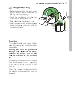
Page 23: ... adjust the screws item Vr until the hood body is level Extraction The cooker hood is more effective when used in the extraction mode ducted to the outside Venting kits may be purchased through your retailer or DIY store and must be ducted to an outside vent of Ø125mm 5 or Ø150mm 6 The ducting used must be manufactured from fire retardent material conforming to the relevant British Standard or DIN...

Page 24: ...culated into the kitchen through the grille outlets on either side of the chimney Fix the flange 10 to the lower opening of the connection 15 Connect the hood air outlet to the flange in the lower part of the junction using a rigid or flexible ø 150 tube by installer s choice Ensure that the charcoal filters have been fitted Rigid pipe is strongly recommended and should be used where possible as t...

Page 25: ...n the ducting run If the distance is greater than 3 metres the efficency of the hood could be impaired The diameter of the ducting spigot on the top of the hood body item 1 is Ø150mm 6 When using Ø125mm 5 ducting it will be necessary to install the ducting adapter item 9 to the Ø150mm 6 outlet on the top of the hood body and the Ø120mm to 125mm ducting collar item 10a supplied If the room where th...

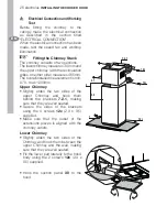
Page 26: ...465mm The overall installed measurement is min 870 max 1200mm Upper Chimney Slightly widen the two sides of the upper Chimney and hook them behind the brackets 7 2 1 making sure that they are well seated Secure the sides to the brackets using the 4 screws 12c 2 9 x 9 5 supplied Make sure that the outlet of the extensions pieces is aligned with the chimney outlets Lower Chimney Slightly widen the t...

Page 27: ......

Page 28: ...www electrolux com 436003739_02 070831 ...

Reviews: