background image

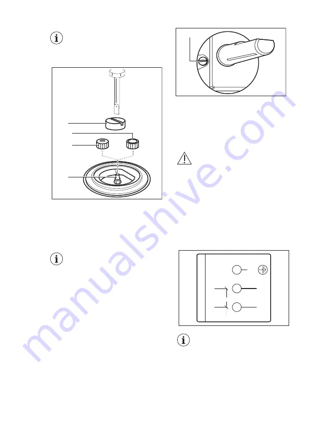
When you assemble each

burner, use the special cap

tool (C) and a screwdriver to

prevent damage to the nuts.

A

B1

B2

C

1. Auxiliary: screw on the nuts with the

diameter of 10 mm (B1), included in

the supply (primary air regulators).

2. Rapid burner: screw on the nuts with

the diameter of 16 mm (B2), included

in the supply (primary air regulators).

Be sure to remove the cap

tool before reassembling the

burners.

3.5 Adjustment of minimum

level

To adjust the minimum level of the

burners:
1. Light the burner.

2. Turn the knob on the minimum

position.

3. Remove the knob. 

4. With a thin screwdriver, adjust the

bypass screw position (A).

A

5. If you change:

• from liquid gas to town gas G110

14mbar, undo the bypass screw

approximately 1 turn.

• from town gas G110 14 mbar to

liquid gas, fully tighten the bypass

screw in.

WARNING!

Make sure the flame does

not go out when you quickly

turn the knob from the

maximum position to the

minimum position.

3.6 Replacing the power supply

cable

Use the same type of power supply

cable. This cable must be connected to

the terminal block following the diagram.

2

3

0

V~

230V~

N

PE

L

If the power supply is

damaged it must be

substituted by a suitable

cable available in the after

sales service.

ENGLISH

9

Summary of Contents for EGC3320NOK

Page 1: ...EGC3320NOK EN Hob User Manual ...

Page 2: ...mation www electrolux com webselfservice Register your product for better service www registerelectrolux com Buy Accessories Consumables and Original spare parts for your appliance www electrolux com shop CUSTOMER CARE AND SERVICE Always use original spare parts When contacting our Authorised Service Centre ensure that you have the following data available Model PNC Serial Number The information c...

Page 3: ...rts are hot If the appliance has a child safety device this should be activated Children shall not carry out cleaning and user maintenance of the appliance without supervision Children aged 3 years and under must be kept away from this appliance when it is in operation at all times 1 2 General Safety WARNING The appliance and its accessible parts become hot during use Care should be taken to avoid...

Page 4: ...ll burners and any electrical heating element and isolate the appliance from the power supply do not touch the appliance surface do not use the appliance If the supply cord is damaged it must be replaced by the manufacturer an authorized Service or similarly qualified persons in order to avoid a hazard Where the appliance is directly connected to the power supply an all pole isolating switch with ...

Page 5: ...of the appliance can get hot Make sure to install a non combustible separation panel under the appliance to prevent access to the bottom 2 2 Electrical Connection WARNING Risk of fire and electric shock All electrical connections should be made by a qualified electrician The appliance must be earthed Before carrying out any operation make sure that the appliance is disconnected from the power supp...

Page 6: ...icable before first use Use this appliance in a household environment Do not change the specification of this appliance Make sure that the ventilation openings are not blocked Do not let the appliance stay unattended during operation Set the cooking zone to off after each use Do not put cutlery or saucepan lids on the cooking zones They can become hot Do not operate the appliance with wet hands or...

Page 7: ...e 2 5 Care and cleaning WARNING Do not remove the buttons knobs or gaskets from the control panel Water may get inside the appliance and cause damage Clean regularly the appliance to prevent the deterioration of the surface material Deactivate the appliance and let it cool down before you clean it Disconnect the appliance from the electrical supply before maintenance Do not use water spray and ste...

Page 8: ...ubject to traction or torsion it does not get in touch with cutting edges or corners it can be easily examined in order to make sure its condition The control of preservation of the flexible pipe consists in checking that it does not show cracks cuts marks of burnings on the two ends and on its full length the material is not hardened but shows its correct elasticity the fastening clamps are not r...

Page 9: ...e knob on the minimum position 3 Remove the knob 4 With a thin screwdriver adjust the bypass screw position A A 5 If you change from liquid gas to town gas G110 14mbar undo the bypass screw approximately 1 turn from town gas G110 14 mbar to liquid gas fully tighten the bypass screw in WARNING Make sure the flame does not go out when you quickly turn the knob from the maximum position to the minimu...

Page 10: ...nd for connection to the appliance To replace the connection cable use only the special cable or its equivalent The cable type is H03V2V2 F T90 Do not let the power cable to heat up to a temperature higher than 90 C The cable must be replaced by a qualified electrician who must make the mains connection as shown below L brown N blue yellow green L N 20 mm WARNING The power supply lead must be repl...

Page 11: ...ice Centres The relevant installation instructions are supplied within the kit package 3 9 Possibilities for insertion The panel installed below the hob must be easy to remove and let an easy access in case a technical assistance intervention is necessary Kitchen unit with door min 20 mm max 150 mm 30 mm 60 mm B A A Removable panel B Space for connections Kitchen unit with oven The electrical conn...

Page 12: ...Ignition candle D Thermocouple 5 2 Ignition of the burner Always light the burner before you put on the cookware WARNING Be very careful when you use open fire in the kitchen environment The manufacturer declines any responsibility in case of the flame misuse 1 Push the control knob down and turn it counterclockwise to the maximum gas supply position 2 Keep the control knob pushed for equal or les...

Page 13: ... switch on the mains after installation or a power cut It is normal The hob is supplied with the progressive valves They make the flame regulation more precise 5 3 Turning the burner off To put the flame out turn the knob to the off position WARNING Always turn the flame down or switch it off before you remove the pans from the burner 6 HINTS AND TIPS WARNING Refer to Safety chapters 6 1 Cookware ...

Page 14: ...lean the hob Be very careful when you replace the pan supports to prevent the hob top from damage 2 After you clean the pan supports make sure that they are in correct positions 3 For the burner to operate correctly make sure that the arms of the pan supports are aligned with the centre of the burner 7 3 Cleaning the hob Remove immediately melted plastic plastic foil sugar and food with sugar If n...

Page 15: ...r cap and crown correctly The flame extinguishes im mediately after ignition Thermocouple is not heat ed up sufficiently After lightning the flame keep the knob pushed for equal or less than 10 sec onds The flame ring is uneven Burner crown is blocked with food residues Make sure that the injector is not blocked and the burner crown is clean 8 2 If you cannot find a solution If you cannot find a s...

Page 16: ... NO 03 IT MADE IN ITALY TYPE IP20 0049 A B C A Stick it on Guarantee Card and send this part if applicable B Stick it on Guarantee Card and keep this part if applicable C Stick it on instruction booklet 9 TECHNICAL DATA 9 1 Hob dimensions Width 290 mm Depth 520 mm 9 2 Bypass diameters BURNER Ø BYPASS 1 100 mm Rapid 50 Auxiliary 28 www electrolux com 16 ...

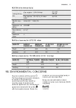
Page 17: ...r TOWN GAS G110 14 mbar BURNER NORMAL POWER kW MINIMUM POWER kW INJECTOR MARK Rapid 2 7 0 75 201 Auxiliary 1 3 0 33 142 10 ENVIRONMENTAL CONCERNS Recycle materials with the symbol Put the packaging in relevant containers to recycle it Help protect the environment and human health by recycling waste of electrical and electronic appliances Do not dispose of appliances marked with the symbol with the...

Page 18: ...www electrolux com 18 ...

Page 19: ...ENGLISH 19 ...

Page 20: ...www electrolux com shop 867345847 D 502019 ...

Reviews: