10
A
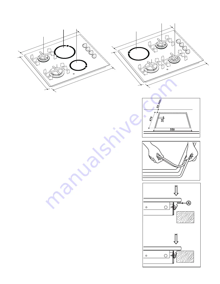
= Auxiliary burner
SR
= Semirapid burner
R
= Rapid Burner
P
= Electric plate
These hobs can be inserted in a built-in kitchen unit
whose depth is between 550 and 600 mm. The hobs
dimensions are shown in the relevant diagram.
The edge of the cut out must have a minimum distance
from the rear wall of 55 mm.
If there are side walls, or sides of the furniture unit near
the hob, the cut out edges must have a minimum
distance of 100 mm.
The hobs can be installed in a kitchen unit with an
opening for insertion whose dimensions are shown in
Fig. 9.
Fitting the hob to the worktop
Before fitting the hob into the cut out, an adhesive seal
must be fitted to the underside outside edge of the hob.
It is essential that no gaps are left in this seal in order to
prevent spillage near the hob seeping into the cabinet
below.
1) Remove the pan supports, the burners caps and
crowns and turn the hob upside down, taking care the
ignition candles are not damaged in this operation.
2) Place the sealing gasket all around the glass top
edge as shown in Fig. 10.
3) Fit the hob in the cut out and push it down until the
glass top and the working top come in touch, as shown
in Fig. 11.
Dimensions are given in millimeters
Building In
a) Sealing gasket
Fig. 9
Fig. 11
FO 2098
FO 2108
Fig. 10
P
P
SR
R
510
615,5
580
Mod. EGM 626
Mod. EGM 636
P
SR
R
510
615,5
580
A
A)
guarnição


