20
electrolux
Fig. 9
"
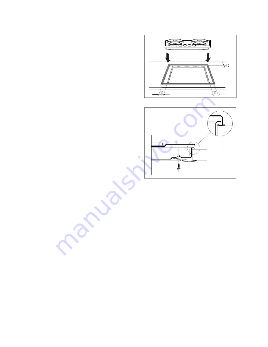
Carry out the building in of the hob
as follows:
• place the seals supplied with the
hob on the front edge of the cut
out. Then, place them at 11 mm
from the side edges and at 10 mm
from the rear edge, as shown in
the diagram, taking care that the
seals meet without overlapping.
• Place the hob in the cut out,
taking care that it is centred.
• Fix the hob with the relevant fixing
clamps, supplied with the
injectors kit (see diagram). When
the screws have been tightened,
the excess seal can be removed.
The edge of the hob forms a double
seal which prevents the ingress of
liquids.
Sealing
gasket
Fig. 8
Summary of Contents for EHE6043
Page 2: ...2 electrolux ...
Page 18: ...18 electrolux Wiring diagram ...
Page 27: ...electrolux 27 ...


