background image

3

ELECTRIC COOKTOP INSTALLATION INSTRUCTIONS

Only certain cooktop models may be installed over 
certain built-in electric oven models. Approved 
cooktops and built-in ovens are listed by the MFG 
ID number and product code (see the insert sheet 
included in the literature package and cooktop 
installation instructions for dimensions).

36” Min.
(91.4 cm) Min.

Use 3/4” (1.9 cm) plywood, 
installed on two runners, flush 
with toe plate. Base must be 
capable of supporting 150 
pounds (68 kg) for 27” models 
and 200 pounds (90 kg) for 
30” models.

Cut an opening in wood base minimum 
4” x 4” (10.2 X 10.2 cm), 2” (5 cm) from 
left side filler panel, to route armoured 
cable to junction box.

*If no cooktop is installed directly over the oven unit, 5” (12.7 cm) maximum is allowed above the floor. 

208/240 Volt junction box 

for built-in oven.

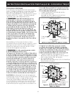
TYPICAL UNDER COUNTER INSTALLATION OF A SINGLE ELECTRIC BUILT-IN OVEN 

WITH AN ELECTRIC COOKTOP MOUNTED ABOVE

Approx. 3”

(7.5 cm)

Cabinet side filler 
panels are necessary to 
isolate the unit from 
adjoining cabinets. 
Cabinet side filler 
height should allow for 
installation of approved 
cooktop models

To reduce the risk of 
personal injury and 
tipping of the wall 
oven, the wall oven 
must be secured to 
the cabinet (s) by 
mounting brackets.

4½” (11.5 cm) 
Max.*

For typical under counter installation of an electric built-in oven with an electric cooktop over.

Approx. 3”

(7.5 cm)

See 

Note 1

Note 1

: 4” x 4” (10.2 X 10.2 cm) opening to route 

armoured cable from cooktop to junction box.

208/240Volt 
junction box 
for Cooktop

Unit will 

overlap 

cutout 

(minimum) 

edges by 

1” (2.5cm)

CUTOUT DIMENSIONS

F. WIDTH

G. DEPTH

H. HEIGHT

27’’ (68.6 cm)

Wall Oven

24 7/8’’ (63.2 cm) Min.

25¼’’ (64.1 cm) Max.

23½’’ (59.7 cm)

27¼’’ (69.2 cm) Min.

28¼’’ (71.8 cm) Max.

30’’ (76.2 cm)

Wall Oven

28½’’ (72.4 cm) Min.

29’’ (73.7 cm) Max.

23½’’ (59.7 cm)

27¼’’ (69.2 cm) Min.

28¼’’ (71.8 cm) Max.

Summary of Contents for EI30EC45KB

Page 1: ...to route armored cable if a panel is present Front Rear Side view Countertop Countertop INSTALLATION AND SERVICE MUST BE PERFORMED BY A QUALIFIED INSTALLER IMPORTANT SAVE FOR LOCAL ELECTRICAL INSPECTOR S USE READ AND SAVE THESE INSTRUCTIONS FOR FUTURE REFERENCE WARNING FOR YOUR SAFETY Do not store or use gasoline or other flammable vapors and liquids in the vicinity of this or any other appliance ...

Page 2: ...binet is Protected by Not Less Than 1 8 0 3 cm Flame Retardant Millboard Covered With Not Less Than No 28 MGS Sheet Steel 0 015 0 4 mm Stainless Steel 0 024 0 6 mm Aluminum or 0 020 0 5 mm Copper 2 1 2 6 4 cm Min From Edge of Cutout to Front Edge of Countertop 18 45 7 cm J Min From Edge of Cooktop to Nearest Combustible Wall Either Side of Unit 12 30 5 cm 10 25 4 cm K Min Recommended Distance Betw...

Page 3: ...t in oven TYPICAL UNDER COUNTER INSTALLATION OF A SINGLE ELECTRIC BUILT IN OVEN WITH AN ELECTRIC COOKTOP MOUNTED ABOVE Approx 3 7 5 cm Cabinet side filler panels are necessary to isolate the unit from adjoining cabinets Cabinet side filler height should allow for installation of approved cooktop models To reduce the risk of personal injury and tipping of the wall oven the wall oven must be secured...

Page 4: ...ircuit fused on both sides of the line time delay fuse or circuit breaker is recommended 40A or 50A DO NOT fuse neutral NOTE Wire sizes and connections must conform with the fuse size and rating of the appliance in accordance with the National Electrical Code ANSI NFPA No 70 latest edition or with CSA standard C22 1 Canadian Electrical Code Part 1 and local local codes and ordinances WARNING An ex...

Page 5: ...r and use ground lead to ground unit in accordance with local codes connect neutral lead to branch circuit neutral conductor in usual manner see Figure 5 If your appliance is to be connected to a 3 wire grounded junction box US only where local code permit connecting the appliance grounding conductor to the neutral white see Figure 4 NOTE TO ELECTRICIAN The armored cable leads supplied with the ap...

Page 6: ...ooktop Nylon spacer Countertop Retainer bracket Figure 8 6 Nylon spacers 2 Retainer brackets Position brackets on unit cutout center line Granite countertop Installation Kit A Granite Countertop Installation kit 903061 9010 can be ordered through a Service Center or by phone at 1 877 ELECTROLUX 1 877 435 3287 Checking Operation Refer to the Use and Care Guide for operation CAUTION Do not touch coo...

Page 7: ... 4 X 8 10 2 cm X 20 3 cm apertura para el cable si existe un panel Parte delantera Parte trasera Vista de lado Mostrador Mostrador LA INSTALACIÓN Y EL SERVICIO DEBEN SER EFECTUADOS POR UN INSTALADOR CALIFICADO IMPORTANTE GUARDE ESTAS INSTRUCCIONES PARA USO DEL INSPECTOR LOCAL DE ELECTRICIDAD LEA Y GUARDE ESTAS INSTRUCCIONES PARA REFERENCIA FUTURA PARA SU SEGURIDAD No amanece ni utilice gasolina u ...

Page 8: ... 28 de acero inoxidable de 0 015 0 4 mm aluminio de 0 024 0 6 mm o cobre de 0 020 0 5 mm 30 76 2 cm min de espacio entre la parte superior del fogón y la parte inferior de un armario de madera o metal sin protección 2 1 2 6 4 cm mín desde el borde delantero del corte hasta el borde delantero de la parte superior del armario k min distancia recomendada entre el borde trasero del corte y el comparti...

Page 9: ...probados Sólo ciertos modelos de tapas de cocina se pueden instalar sobre ciertos modelos de hornos eléctri cos empotrados Las tapas de cocina y los hornos empotrados se mencionan por su número de identificación MFG ID y código de producto ver la planilla que se incluye en el paquete de literatura y las instrucciones de instalación de la cocina donde están detalladas las dimensiones Para reducir e...

Page 10: ...aque todo el material usado en el embalaje de la estufa antes de conectar el suministro eléctrico a la estufa 3 Observe todos los códigos y reglamentos pertinentes 4 Deje estas instrucciones con el consumidor Nota importante al consumidor Conserve estas instrucciones y el Manual del usuario para referencia futura INSTRUCCIONES IMPORTANTES DE SEGURIDAD Asegúrese de que su estufa sea instalada y pue...

Page 11: ... poner a tierra la unidad de acuerdo a los códigos locales conectar el neutro al circuito de bifurcación conductor neutro de manera usual Ver Figura 5 Si su electrodoméstico va a ser conectado a una caja de conexión puesta a tierra de 3 cables en los estados unidos solamente donde los códigos locales permitan conectar el conductor de poner a tierra electrodoméstico con el neutro blanco ver Figura ...

Page 12: ...ón Superficie del armario Ménsula de sostenimiento Tornillos Figura 6 El kit de instalación para una cubierta en granito Un kit de instalación 903061 9010 para una cubierta de granito se puede pedir a través de un centro de servicio o al teléfono en 1 877 4ELECTROLUX 1 877 435 3287 Revisión de operación Consulte el Manual del Usuario para las instrucciones de funcionamiento No toque el cristal o l...

Page 13: ...X 8 10 2 cm x 20 3 cm pour laisser passer le câble armé si il y a un panneau Avant Arrière Vue de côté Comptoir Comptoir UN INSTALLATEUR QUALIFIÉ DOIT EFFECTUER L INSTALLATION ET LE SERVICE IMPORTANT CONSERVEZ CES INSTRUCTIONS POUR LES INSPECTEURS LOCAUX LISEZ CES INSTRUCTIONS ET CONSERVEZ LES POUR RÉFÉRENCES ULTÉRIEURES POUR VOTRE SÉCURITÉ N entreposez et n utilisez pas d essence ou d autres prod...

Page 14: ... ou en métal est protégée par un celloderme retardateur de flammes d un minimum de 1 8 0 3 cm recouvert d une feuille de métal MSG No 28 d acier inoxydable d un minimum de 0 015 0 4 mm d aluminium de 0 024 0 6 mm ou de cuivre de 0 020 0 5 mm Minimum de 2 6 4 cm du re bord de découpage au rebord avant du dessus de comptoir 18 45 7 cm Minimum de J du rebord de la plaque de cuisson au mur en matériel...

Page 15: ...le coup de pied La base doit pouvoir supporter 150 lbs 68 kg pour les modèles 27 et 200 lbs 90 kg pour les modèles 30 Découpez une ouverture de 4 X 4 10 2 cm X 10 2 cm à 2 5 cm du côté gauche du plancher pour la sortie du câble armé de l appareil vers la boîte de jonction Il faut fermer les côtés de l habitacle par des panneaux de bois pour isoler l appa reil des armoires de chaque côté La hauteur...

Page 16: ...utre NOTE Le calibre des fils et leurs connexions doivent être conformes à la capacité des fusibles et à la capacité nominale de l appareil selon le National Electrical Code ANSI NFPA No 70 dernière édition ou avec la norme ACNOR C22 1 Partie 1 du Code canadien d électricité et les codes et les règlements locaux N utilisez pas de rallonge électrique avec cet appareil Son utilisation peut causer un...

Page 17: ... les fils blanc et vert des autres et utilisez le fil de mise à la terre pour mettre à la terre l appareil conformément aux codes locaux branchez le conducteur neutre de manière habituelle au circuit neutre voir la figure 5 Si l appareil doit être branché à un câble à 3 fils aux États Unis seulement où les codes locaux permettent la connexion du fil de mise à la terre du châssis au neutre blanc Vo...

Page 18: ...ectuosités dans le matériel ou la fabrication de cet appareil Référez vous au Manuel d utilisation pour les numéros de téléphone du service Installation de la plaque de cuisson 1 Vérifiez si la plaque de cuisson est endommagée Veillez également à ce que toutes les vis de la plaque de cuisson soient bien serrées Figure 6 2 Installer les supports de fixation voir figure 7 Les supports de fixation DO...

Page 19: ...19 INSTRUCTIONS D INSTALLATION POUR PLAQUE DE CUISSON ÉLECTRIQUE Notes ...

Page 20: ...20 INSTRUCTIONS D INSTALLATION POUR PLAQUE DE CUISSON ÉLECTRIQUE Notes ...

Reviews: