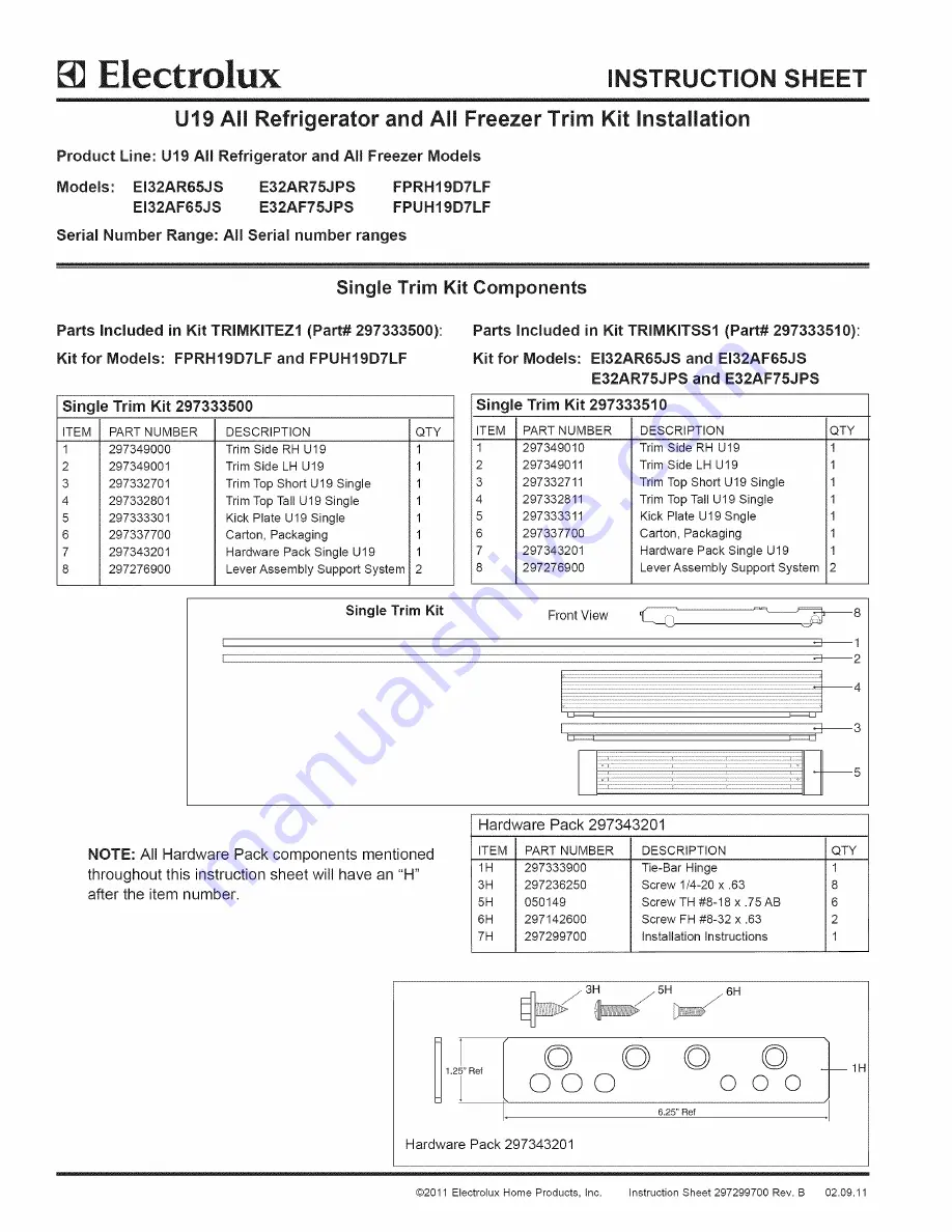
background image

Summary of Contents for EI32AF65JS

Page 1: ...I Part 297333510 Kit for Models EI32AR65JS and EI32AF65JS E32AR75JPS and E32AF75JPS Single Trim Kit 297333510 ITEM PART NUMBER 1 297349010 2 297349011 3 297332711 4 297332811 5 297333311 6 297337700 7 297343201 8 297276900 DESCRIPTION QTY Trim Side RH U19 1 Trim Side LH U19 1 Trim Top Short U19 Single 1 Trim Top Tall U19 Single 1 Kick Plate U19 Sngle 1 Carton Packaging 1 Hardware Pack Single U19 1...

Page 2: ...49011 4 297332710 5 297332810 6 297333310 7 297337700 8 297343200 9 297276900 DESCRIPTION QTY Center Trim U19 1 Trim Side RH U19 1 Trim Side LH U19 1 Trim Top Short U19 Dual 1 Trim Top Tall U19 Dual 1 Kick Plate U19 Dual 1 Carton Packaging 1 Hardware Pack Dual U19 1 LeverAssembly Support System 4 Front View Double Trim Kit tml I _4 NOTE All Hardware Pack components mentioned throughout this instru...

Page 3: ...SI Part 297333510 Trim Kit Dimensions 75 00 _ 06 1905 ram 79 00 06 2006 5 1 5mm 641mm j rain _ _ 33 00 032 _ 838 8mm 75 09 1907 ram 34 74 882 ram _ _ J 34 74 __ 882 mm _ l m 79 09 2009 ram 2011 Etectrolux Home Products Inc Instruction Sheet 297299700 Rev B 02 09 11 ...

Page 4: ...lasses when using power tools Adjustable Wrench to fit 1 1 4 3 8 Socket Wrench 7 16 Socket Wrench Step Ladder Tape Measure min 7 length Drill 1 8 Bit Before You Begin Be careful when unpacking components Do not use sharp objects when removing packaging material This may scratch the surface of trim components Use extreme care when handling the metal trim pieces Corners are very sharp and easily dam...

Page 5: ...stall Single and Dual Installations 3 a Lie unit on its back on packaging material or a drop cloth to prevent damage b Remove 3 screws from each side and discard See Figure 3 c Remove and save both plastic leg levelers to use in the next step Figure 3 a Attach the current leg leveler to leveling system The leg leveler is a common part that will work on both bottom sides of the unit See Figure 4 b ...

Page 6: ...ps driver See Figure 8 3 8 Gap 3H Figure 5 3 8 Gap Between Units 3 8 Center Strip Item 1 Dual kit Figure 6 Item 1H Figure 8 Trim Kit installation Single Unit installation 6 Remove outer screw from top hinge using a 3 8 socket driver or wrench and save for later Install mounting bracket with one screw mounted to inside hole using a 3 8 socket See Figure 9 Screw Figure 9 Side Trim installation Singl...

Page 7: ...n top trim and attach with 3 8 socket See Figure 12 H Figure 11 Figure 12 10 75 1905mm High Opening With Top Trim Single and Dual Installations a Slide units into place Adjust height so top trim height reaches 75 09 1907mm Center units in opening and level See Step 12 for leveling instructions See Figures 13 and 14 b Drill 1 8 3mm pilot holes and fasten screws with a Phillips driver to kitchen cab...

Page 8: ... Screws Leg Leveler Figure 16 13 Hinge Adjustment See Figure 16 Single and Dual Installations a The bottom hinge is designed to make final minor adjustments for door to door and door to cabinet alignment b Hinge will move side to side 3 32 and raise up 1 8 Use a 7 16 socket or open end wrench to raise or lower the door Use a 3 8 socket and a Phillips screwdriver to loosen bottom hinge Shift door l...

Reviews: