


CONNECTION TO THE MAINS SUPPLY THE
APPLIANCE MUST BE CONNECTED IN
ACCORDANCE WITH THE RULES IN FORCE,
AND ONLY BY AN AUTHORIZED ELECTRICAL
INSTALLER.
WARNING:THIS APPLIANCE MUST BE
EARTHED
Check that the power rating of the mains supply
and of the sockets are suitable for the maximum
power of the appliance as indicated on the
specification plate. If the appliance does not come
already fitted with a plug, fit a regulation plug to the
cable which is capable of taking the power indicated
on the specification plate (fig. 8 B ).
The earth wire is yellow/green.
If the plug fitted
to the appliance, and the socket, are incompatible,
get a profesionnally qualified person to fit the correct
type of plug. If an appliance is not equipped with
supply cable and plug, the power supply must be
fitted with a disconnect switch in which the distance
between contacts permits total disconnection in
accordance with overvoltage category III, as required
by installation regulations.
The yellow/green earth wire should not be
controlled by the switch.
The plug used for mains supply connection should
be easy to get at, once the appliance is in position.
Important:
position the mains supply cable so that
it is never subjected to a temperature which is more
than 50°C above ambient temperature.
The electrical safety of the appliance can only be
guaranteed when it has been correctly connected
to an efficient earthed power supply, as laid down
in the regulations for electrical safety.
Important:
the manufacturer cannot be held
responsible for any damage to persons or objects
due to the lack of an earth connection.
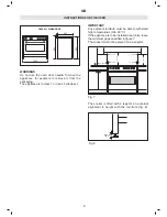
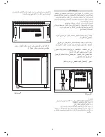
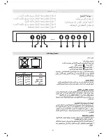
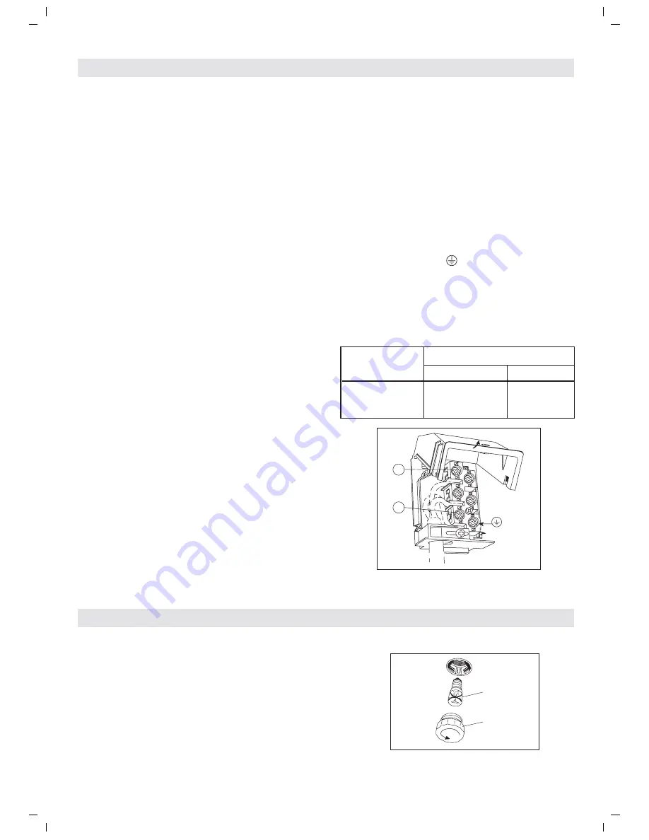
REPLACEMENT OF THE CABLE (fig. 17).
ALWAYS UNPLUG THE PLUG FROM THE
CURRENT SOCKET OR SWITCH OFF THE
CURRENT ON THE POWER SUPPLY LINE BY
MEANS OF THE MAINS CIRCUIT SWITCH,
BEFORE CARRYING OUT ANY MAINTENANCE
ON THE OVEN.
If the cable is damaged, fit a replacement in the
following way:
- remove the mains cable and replace it with one
of the same length which is rubber insulated and
suitable for the power rating of the appliance.
The yellow/green earth wire, which must be
connected to terminal , has to be about 10 mm
longer than the other wires; the blue neutral wire
has to be connected to the terminal marked with
letter N. The live wire must be connected to the
terminal marked with letter L.
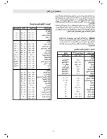
TYPE AND SECTION OF SUPPLY CABLE
Applance type Alimentation monophasée 220-240 V~
Type of cable section
All gas + elect. oven Rubber H05 RR-F 3 x 1,5 mm
2
Rubber H05 RN-F
L
2
1
3
4
5
N
E 14
25 W - 230 V~
T300°C
A
Fig. 18
*
Fig. 17
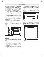
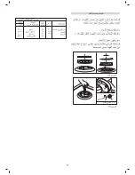
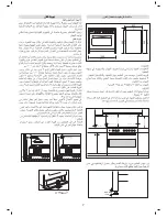
WARNINGS
Isolate the cooker from the electricity supply before
attempting to replace the oven lamp.
The oven lamp
is of a special type designed to
withstand high temperatures. To replace it, proceed
as follows: remove the protective glass
(A)
and
replace the burnt-out bulb with one of the same
type (fig. 18).
Re-fit the protective glass.
GB
13
ELECTRICAL CONNECTION
APPLIANCE MAINTENANCE
Summary of Contents for EKM 101199 X
Page 1: ...Instructions booklet mod EKM 101199 X ...
Page 15: ...L 2 1 3 4 5 N A H05 RR F H05 RN F 10 ...
Page 16: ...C C C 9 ...
Page 17: ...8 A ...
Page 18: ...1000 600 960 900 min 100cm2 C 7 REG MAX 15mm C ...
Page 19: ...B A C 6 10 2 0 3 0 4 0 5 0 6 0 7 0 8 0 9 0 1 0 0 11 0 1 2 0 0 stop ...
Page 20: ...MAX 5 6 0 80 1 0 0 1 2 5 1 5 0 1 7 5 2 0 0 2 2 5 M A X 0 0 ...
Page 21: ...4 ...
Page 22: ...Ø Ø Ø Ø 3 1 1 2 2 4 4 5 5 6 6 7 7 8 8 9 9 3 3 ...
Page 23: ... C 2 ...
Page 24: ...Tip Montagnani Italy Cod 538515 0310 MADE IN ITALY ...


