background image

SERVICE INSTRUCTION

COLD

21

FREEZER

NOFROST

ERF2000

This instruction replaces publication no.
599 xx xx-xx

Publication number

599 51 83-06

03-10-21

SV/SERVICE

DT/MA/AN

DISTRIPARTS AB

BOX 501
S-562 80 NORRAHAMMAR
TEL 036-31 80 00

Telefax 036-31 81 10
Telefax 036-31 80 88

B

TABLE OF CONTENTS……………………………………………….  2

1 REGULATION………………………………………………………..  3
2 THE ERF2000-PANEL……………………………………………...  3
3 ERF2000-FUNCTIONS………………………………………….….  4
4 SPECIAL FUNCTIONS……………………………………………..   6
5 MANUAL DEFROSTING……………………………………………  6
6 DISASSEMBLY COLD MODULE………………………….………  7
7 SENSORS……………………………………………………………  9
8 PRINTED CIRCUIT BOARD (PCB)………………………………. 10

Summary of Contents for ERF2000

Page 1: ...83 06 03 10 21 SV SERVICE DT MA AN DISTRIPARTS AB BOX 501 S 562 80 NORRAHAMMAR TEL 036 31 80 00 Telefax 036 31 81 10 Telefax 036 31 80 88 B TABLE OF CONTENTS 2 1 REGULATION 3 2 THE ERF2000 PANEL 3 3 ERF2000 FUNCTIONS 4 4 SPECIAL FUNCTIONS 6 5 MANUAL DEFROSTING 6 6 DISASSEMBLY COLD MODULE 7 7 SENSORS 9 8 PRINTED CIRCUIT BOARD PCB 10 ...

Page 2: ...ng the temperature 3 4 Action Freeze Freezing 3 5 Temperature alarm 3 6 Door alarm 3 7 Door switch 3 8 Error indication on the ERF2000 panel 4 Special functions 4 1 Cooler mode 4 2 Super cooling 4 3 Demo mode 5 Manual defrosting 6 Disassembly cold module 7 Sensors 7 1 General 8 Printed Circuit Board PCB 8 1 Replacement of Printed Circuit Board PCB ...

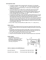
Page 3: ...tops immediately When starting the cabinet when the temperature inside is warmer than 0 C the defrosting starts 8 minutes after start 2 The ERF2000 panel A ON OFF button lights when running B Freezer thermometer C Temperature selector Thermostat D Temperature selector Thermostat E Freezing button freezing lamp lights when freezing F Warning lamp flashes on alarm reset button for alarm A B C D E F ...

Page 4: ...pushing on or The selected temperature is always displayed flashing After ca 5 seconds the flashing stops and the thermometer displays the temperature in the freezer If the or button is being pushed once the selected value shows in the display When the refrigerator is restarted the temperature needs not to be reselected The ERF2000 electronic is automatically set on the latest selected temperature...

Page 5: ...ue to the fact that the electronic circuit has a memory function After one push on the reset button the thermometer will during 5 seconds show the highest temperature reached in the freezer and the red warning lamp will turn off When Cooler mode is activated AEG the alarm limit is 17 C see point 4 1 3 6 Door alarm The door alarm activates when the door has been opened more than 80 seconds This is ...

Page 6: ...der temperature and hold them for 2 3 seconds To enable the activation of this function the product has to be in operation and the air sensor temperature has to be warmer than 10 C The demo mode can be deactivated on two different ways By pressing the buttons for ON OFF and the temperature selection button for colder temperature for 5 seconds the freezer goes back to normal operation By power cut ...

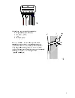
Page 7: ... around the corrugated drainage hose and the cable picture 2 Release the corrugated hose from the lower hose 5 Unscrew the 2 screws holding the module and pull it out 6 When the insulation on top of the evaporator has been removed all details are easy to access picture 3 A Evaporator B Defrost heater C Air sensor D Thermostatic switch E Evaporator sensor 7 The quick coupling is mounted on the lowe...

Page 8: ...The reassemble is done in the opposite order NOTE Before the cover the insulation and the upper air channel is reassembled check that the cage G for the drainage hose is not loose from from the module H Check also that the corrugated drainage hose J is pressed against the module picture 6 E C F B 5 G H J 6 ...

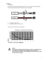
Page 9: ...rs characteristic are shown below NOTE It is extremely important that the different entries are completely tight If the entries are not tight heat is transferred into the cabinet This will have an influence on the regulation of the freezer and on what the thermometer displays 0 10000 20000 30000 40000 50000 60000 70000 80000 90000 100000 40 30 20 10 0 10 20 30 40 Resistance Temperature for NTC sen...

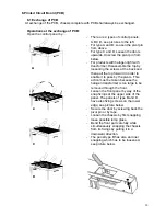
Page 10: ...nd then pull the top forward in order to enable it to pass by the pivots This action must be taken because the halogen transformer is too large to be removed through the front Loosen the front panel by way of the snap fixings at the upper side of the panel The panels of type B and D have also fixing screws on the lower edge see picture below Secure the door by screwing back the pivot pin or by tap...

Reviews: