background image

22

G

G

C

CO

OM

MM

MIIS

SS

SIIO

ON

NIIN

NG

G

G

G..1

1

P

Prre

elliim

miin

na

arryy cch

he

ecckkss,, a

ad

djju

ussttm

me

en

nttss a

an

nd

d

o

op

pe

erra

attiio

on

na

all tte

essttss

W

WA

AR

RN

NIIN

NG

G

These operations must only
be carried out by specialized
technicians provided with
adequate personal
protection equipment (e.g.
safety footwear, gloves,
glasses, etc.), tools and
suitable ancillary equipment
with the appliance switched
off and cold.

Electrical and plumbing checks

Before starting the machine:
• check correct connection of the electrical wires that feed

the machine;

• make sure the power supply voltage and frequency match

the data given in the technical data table (D.1

Main

technical characteristics);

• check correct connection of the water supply and drain

pipes (see paragraph F.6

Plumbing connections);

• make sure all the guards, safety devices and emergency

switches are in place and efficient.

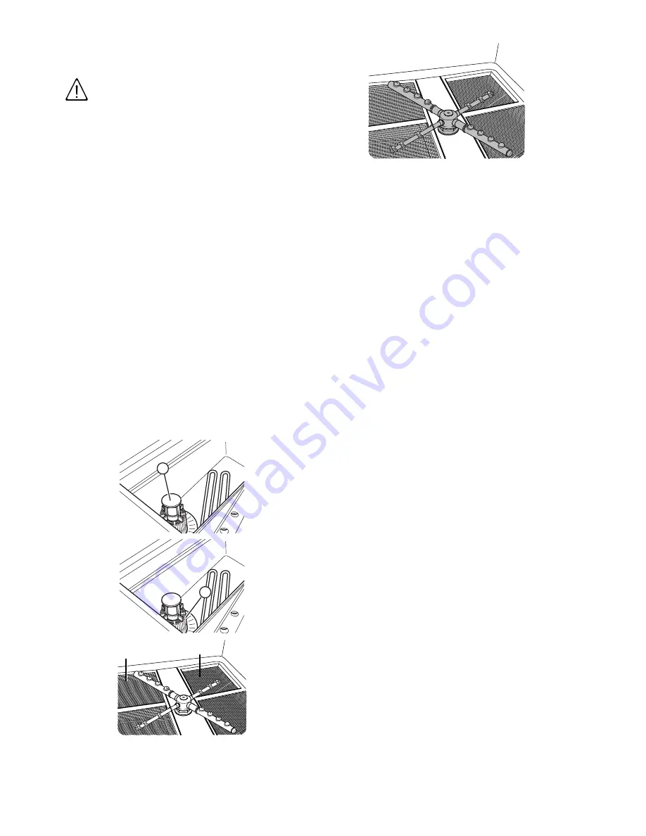
Check the positioning of tank components

• Make sure that, the overflow “A“, the tank filter “B“, and the

flat filters “C“ are correctly fitted.

• Make sure the upper and lower wash and rinse arms are

correctly fitted.

A

B

C

C

Summary of Contents for EUC1WS

Page 1: ...U Un nd de er r C Co ou un nt te er r D Diis sh hw wa as sh he er r EUC1WS NUC1WS ZUC1WS EUC3WS NUC3WS ZUC3WS E EN N Installation and operating manual Original instructions 595665I02 2016 09 ...

Page 2: ...ag gr ra am m EI Power supply entry WI Water Inlet pipe with 3 4 G fittings XD Inlet pipe for detergents EQ Equipotential screw D Drain pipe with internal diameter 40 mm Only for model with free fall drainage 20 mm Only for model with drain pump ...

Page 3: ...3 600 820 46 508 46 XD D WI 35 5 54 4 40 15 184 212 5 236 5 38 61 59 431 59 980 D D WI EI EQ 20 MAX 610 EI 162 30 EQ 645 Ø 40 Ø 20 750 1000 0 100 ...

Page 4: ...arefully kept in the place where the machine is used so that it is always at hand for consultation in case of doubts or whenever required If after reading this manual there are still doubts regarding machine use do not hesitate to contact the Manufacturer or the authorised Service Centre to receive prompt and precise assistance for better operation and maximum efficiency of the machine During all ...

Page 5: ...dling operations 16 E 4 Shifting 16 E 5 Placing the load 16 E 6 Storage 16 F INSTALLATION AND ASSEMBLY 17 F 1 Introduction 17 F 2 Customer responsibilities 17 F 3 Characteristics of the installation place 17 F 4 Positioning 17 F 5 Disposal of packing 18 F 6 Plumbing connections 18 F 7 Plumbing circuits 19 F 8 Electrical connections 20 F 8 1 Connections provided for energy control 20 F 9 Safety dev...

Page 6: ...inactivity 29 K 4 Boiler drainage 29 K 5 Preventive maintenance 29 K 6 Introduction 29 K 7 Waste storage 29 K 8 Procedure regarding appliance dismantling macro operations 29 L TROUBLESHOOTING 30 L 1 Common faults 30 L 2 Alarms 30 ...

Page 7: ... been given supervision or instruction concerning use of the appliance in a safe way and understand the hazards involved Do not let children play with the appliance Keep all packaging and detergents away from children Cleaning and user maintenance shall not be made by children without supervision C CA AU UT TI IO ON N Do not wash the appliance with direct or high pressure jets of water W WA AR RN ...

Page 8: ...ne installation adjustment use maintenance cleaning repair and transport personnel Manufacturer Electrolux Professional SpA or any other service centre authorised by Electrolux Professional SpA Operator for normal machine use an operator who has been informed and trained regarding the tasks and hazards involved in normal machine use After sales service or specialised technician an operator instruc...

Page 9: ... Machine type UC Under counter 3 6 Options 1 Single phase 3 Three phases A Atmospheric DP Drain pump WS Water Softener DD Detergent pump G Detergent pump rinse aid pump drain pump MS Multi rack support R Additional rack UK UK market B B 7 7 R Re es sp po on ns siib biilliit ty y The Manufacturer declines any liability for damage and malfunctioning caused by non compliance with the instructions con...

Page 10: ...ird parties with the permission of Electrolux Professional SpA B B 1 11 1 P Pe er rs so on na all p pr ro ot te ec ct tiio on n e eq qu uiip pm me en nt t S Su um mm ma ar ry y t ta ab blle e o of f t th he e P Pe er rs so on na all P Pr ro ot te ec ct tiio on n E Eq qu uiip pm me en nt t P PP PE E t to o b be e u us se ed d d du ur riin ng g t th he e v va ar riio ou us s s st ta ag ge es s o of ...

Page 11: ... do not remove the safety devices do not use water to extinguish fires placed on electrical parts D Da an ng ge er r M Me ea an niin ng g danger of crushing hands danger of burns danger of electrocution shown on electrical parts with indication of voltage W WA AR RN NI IN NG G Do not remove tamper with or make illegible the safety danger and instruction signs and labels on the machine C C 4 4 E En...

Page 12: ...ces Nevertheless through this manual the Manufacturer has taken steps to inform operators of such risks carefully indicating the personal protection equipment to be used by them Sufficient spaces are provided for during the machine installation stages in order to limit these risks To preserve these conditions the areas around the machine must always be kept free of obstacles e g ladders tools cont...

Page 13: ...imbs during the hood closing operation Tipping of loads When handling the machine or the packing containing it using unsuitable lifting systems or accessories or with the load unbalanced Chemical Contact with chemical substances e g detergent rinse aid scale remover etc without taking adequate safety precautions Therefore always refer to the safety cards and labels on the products used ...

Page 14: ...noise emission values have been obtained according to EN ISO 11204 4 40 00 0 4 41 15 5V V 3 3N N 2 22 20 0 2 24 40 0V V 3 3 2 22 20 0 2 24 40 0V V 1 1N N C S C S C S 3 35 kW 3x2 5 mm2 20A 1P N 5 35 kW 5x1 5 mm2 16A 3P N 4x2 5 mm2 20A 3P 3x4 mm2 32A 1P N 5 65 kW 3x4 mm2 32A 1P N 7 35 kW 5x2 5 mm2 25A 3P N 4x4 mm2 32A 3P 3x6 mm2 40A 1P N C Power supply cable S On Off switch NOTE Standard cycle time ...

Page 15: ...ollers or differential current protection devices to activate automatic power disconnection an isolation controller must be provided for indicating a possible first earth fault of a live part unless a protection device is supplied for switching off the power in case of a such a fault This device must activate an acoustic and or visual signal which must continue for the entire duration of the fault...

Page 16: ...use the type of equipment most suitable for characteristics and capacity e g electric pallet truck or lift truck cover sharp edges Before lifting send all operators to a safe position and prevent persons from entering the handling area make sure the load is stable make sure no material can fall during lifting Manoeuvre vertically in order to avoid impacts handle the machine keeping it at minimum h...

Page 17: ...m adducting for the electrical connection between the workplace electric panel and the equipment the water supply and drain connections and other connections as indicated in D 1 Main technical characteristics and in the paragraph F 6 Plumbing connections F F 3 3 C Ch ha ar ra ac ct te er riis st tiic cs s o of f t th he e iin ns st ta alllla at tiio on n p plla ac ce e The machine is designed for ...

Page 18: ...ors NOTE The parts in wood and cardboard can be disposed of respecting the current regulations in the country where the machine is used F F 6 6 P Pllu um mb biin ng g c co on nn ne ec ct tiio on ns s Connect the appliance water supply pipe WI see the Installation diagram to the mains fitting a cut off tap the filter provided and a pressure gauge between the appliance and the mains see figure below...

Page 19: ...ts s Appliance with atmospheric water supply without drain pump Appliance with pressure water supply without drain pump Appliance with atmospheric water supply with drain pump Appliance with pressure water supply with drain pump L LE EG GE EN ND D WI Water inlet D Drain M1 Wash pump M2 Drain pump AG Air Gap YV1 Filling solenoid valve V1 Non return valve hot circuit AG AG ...

Page 20: ...e see D 1 Main technical characteristics table connect the three phases to terminals 1 3 and 5 and the earth wire to the terminal P Po ow we er r s su up pp plly y 2 22 20 0 2 23 30 0V V 1 1N N Open the power supply terminal board and insert the jumpers provided as follows two jumpers between terminals 1 3 5 and another two between terminals 2 4 and 6 Using a suitable power supply cable see D 1 Ma...

Page 21: ...nse aid It dispenses 0 4 g in 4 sec at each rinse Dispenser operating time may be changed following the instructions given in the next paragraph H 2 Setting the dispensers Insert the hose supplied in the rinse aid container F Fiig g 1 1 A Au ut to om ma at tiic c d diis sp pe en ns se er r o ov ve er rv viie ew w There is a ready made impression N to be perforated 8 mm for positioning the detergen...

Page 22: ...ectrical and plumbing checks Before starting the machine check correct connection of the electrical wires that feed the machine make sure the power supply voltage and frequency match the data given in the technical data table D 1 Main technical characteristics check correct connection of the water supply and drain pipes see paragraph F 6 Plumbing connections make sure all the guards safety devices...

Page 23: ... 182 the d de et te er rg ge en nt t d diis sp pe en ns se er r only operates during filling electrovalve operation for restoring the boiler level terminals 7 7 9 9 of the main terminal board are powered at the same time if the setting is rai 61 the r riin ns se e a aiid d d diis sp pe en ns se er r only operates during filling electrovalve operation for restoring the boiler level terminals 8 8 9 ...

Page 24: ...the range whereas others are available only on some versions O On n O Of ff f This button indicates equipment status on or off When the equipment is on the button indicator is lit up R Re eg ge en ne er ra at tiio on n c cy yc clle e When on the display appears rEG press this button to activate the regeneration cycle of the water continuous softener D Dr ra aiin n s se ellf f c clle ea an niin ng ...

Page 25: ...utton J J 4 4 W Wa as sh h c cy yc clle es s The wash cycle includes one wash with hot water and detergent min 55 and one rinse with hot water and rinse aid min 82 T Ta ab blle e o of f t tiim me es s s st ta an nd da ar rd d c cy yc clle e t tiim me e w wiit th h s su up pp plly y w wa at te er r a at t 5 50 0 EUC WS NUC WS ZUC WS 120 sec 180 sec A device lengthens the cycle time if the water in ...

Page 26: ...re to remove the residuals of detergent possibly used for manual prewash can cause malfunctioning of the dishwasher and compromise washing results I IM MP PO OR RT TA AN NT T Change the water in the tank at least twice a day J J 6 6 T Ty yp pe e o of f r ra ac ck ks s a an nd d llo oa ad diin ng g YELLOW rack for 18 plates with maximum diameter of 240 mm BLUE rack for glasses the glasses should be...

Page 27: ...nse arms I and O are not symmetrical the rinse arm with raised ring O should be fitted onto hub socket Upon completion of cleaning operations replace the parts removed previously K K 1 1 1 1 C Clle ea an niin ng g t th he e e ex xt te er riio or r s su ur rf fa ac ce es s Before carrying out any cleaning operations turn off the power at the mains C CA AU UT TI IO ON N Clean the stainless steel sur...

Page 28: ...pproximately 0 5 Kg of coarse salt NaCI the amount necessary to fill the salt container up to the rim into container A C CA AU UT TI IO ON N Only salt may be placed in the salt container Do not introduce any other chemical substances such as detergent rinse aid or descaling agent since these would inevitably damage the appliance Such damage invalidates any warranty and relieves the manufacturer of...

Page 29: ... general check up of the state of the appliance K K 6 6 I In nt tr ro od du uc ct tiio on n W WA AR RN NI IN NG G Dismantling operations must be carried out by qualified personnel W WA AR RN NI IN NG G Work on the electrical equipment must only be carried out by a qualified electrician with the power supply disconnected K K 7 7 W Wa as st te e s st to or ra ag ge e At the end of the product s life...

Page 30: ...er temperature is not less than 50 2 Check if the amount of product dispensed by the detergent dispenser is excessive see H 2 Setting the dispensers paragraph 3 Ensure that the tank has not been cleaned with unsuitable cleaners Drain the tank and rinse thoroughly before new wash cycles 4 If a foaming detergent has been used drain and refill the tank with water until the foam disappears SMEARS OR S...

Page 31: ......

Page 32: ...Electrolux Professional SPA Viale Treviso 15 33170 Pordenone www electrolux professional com ...

Reviews: