SOI/DT 2002-07 eb
28
599 35 36-69
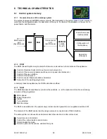
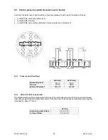
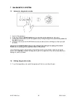
6.2 Door interlock
There are two types of door interlock:
•
voltmetric with PTC: it is always necessary to wait from 1 to 2 minutes from the end of the cycle before
opening the door.
•
instantaneous: the door can be opened as soon as the cycle ends.
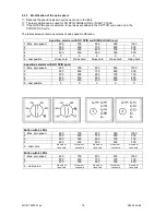
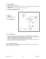
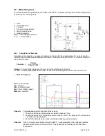
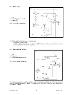
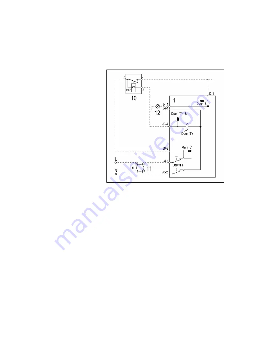
6.3 Voltmetric interlock with PTC
1 PCB
10 Door interlock
11 Suppressor
12 (“Door locked” pilot lamp)
ON/OFF = Main switch
(Programme selector)
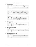
6.3.1 Operating principle
•
When the washing programme is started by pressing the START/PAUSE button, the bimetal PTC
(contacts 3-5) is powered by the triac on the PCB: after 2 – 4 seconds, this closes the switch (5-4) which
powers the electrical components of the appliance (only if the door is closed).
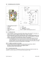
•
The door interlock prevents the door opening while the appliance is in operation.
•
At the end of the washing programme, the PCB disconnects the device from the power supply, but the
door remains locked for 1 to 2 minutes (PTC cooling time).
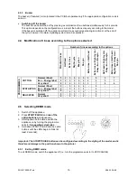
6.3.2 “Door locked” pilot lamp
Certain models might feature a pilot lamp that lights to indicate that the door is locked. This pilot lamp
switches off when the door can be opened.


