SOI/DT 2002-07 eb
29
599 35 36-69
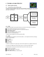
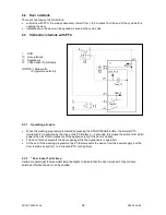
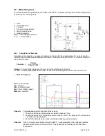
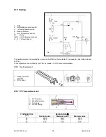
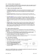
6.4 Instantaneous door interlock
1. PTC protecting the solenoid
2. Solenoid
3. Levers
4. Cam
5. Bimetal PTC
6. Main switch contacts
7. Pawl
1. PCB
10. Door interlock
11. Suppressor
12. (“Door locked” pilot lamp)
ON/OFF = ON/OFF switch (Programme selector)
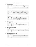
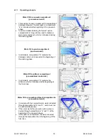
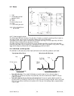
6.4.1 Operating principle
•
When the appliance is switched on, the ON/OFF switch closes and the bimetal PTC (contacts 4-2) is
powered, but the cam takes a position that prevents the coming out of the pawl.
•
When the programme starts (START), the PCB transmits a 20-msec voltage signal to contacts 4-3 of
the solenoid (at least 6 seconds must elapse after switching on). This signal causes the cam turn one
position - in this way the pawl blocking the device cursor is lifted - and, at the same time, it closes the
contacts 4-5 (main switch), which power all the components in the appliance.
•
At the end of the programme, the PCB transmits two 20-msec signals (at an interval of 200 msec).
-
the first signal causes the cam turn one more position, however without releasing the pawl.
-
the second signal (which is transmitted only if the system functions correctly) causes the cam turn
one further position. In this way the pawl retracts to its housing and the door interlock is released;
at the same time the contacts of the main switch (4-5) are opened.
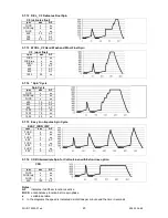
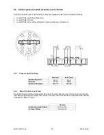
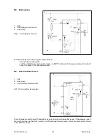
6.4.2 Conditions necessary for door release
Before transmitting the door release signals, the main PCB checks for the following conditions:
-
the drum must be stationary (no signal from the tachometric generator)
-
the water level must not be higher than the lower edge of the door
-
the water temperature must not exceed 40°C.
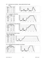
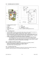
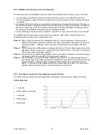
6.4.3 Automatic release device
In the event of a power failure, if the appliance is switched off or if the solenoid should malfunction, the
bimetal PTC cools over a period of 1 to 4 minutes, and then releases the door.


