SOI/DT 2002-07 eb
31
599 35 36-69
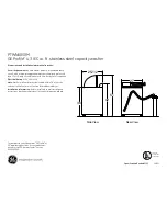
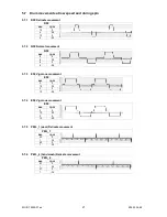
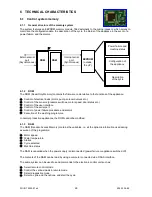
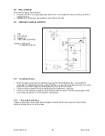
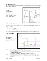
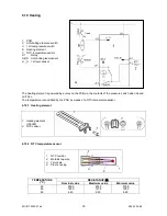
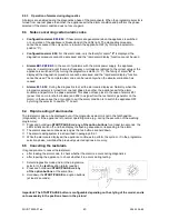
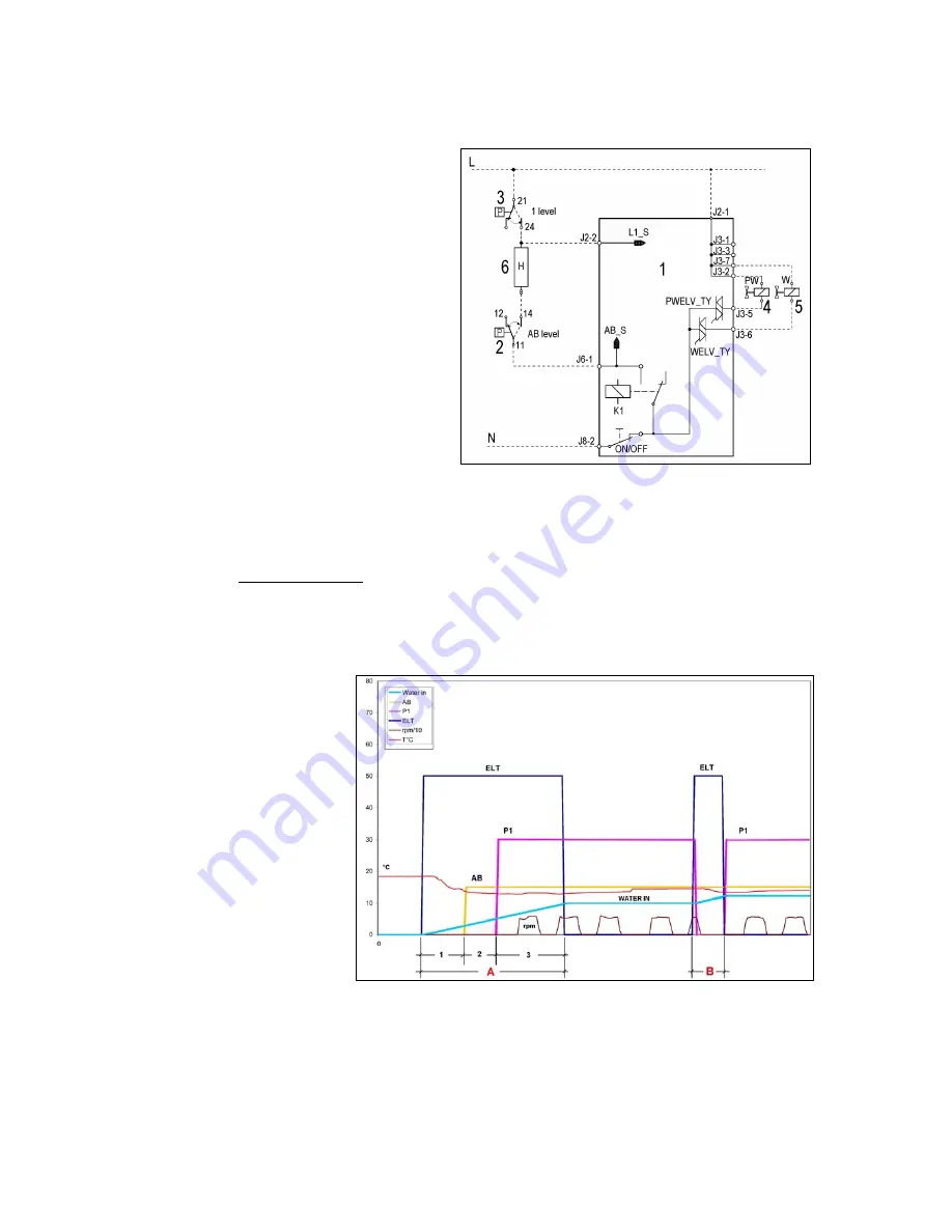
6.6 Water fill system
The solenoid valves are powered by the PCB via two triacs. The status of the pressure switch (empty/full) is
detected by two “sensing” lines.
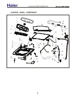
1. PCB
2. Anti-boiling level
3. 1st
level
4. Pre-wash
solenoid
valve
5. Wash solenoid valve
6. Heating element
AB_S Anti-boiling level sensor
L1_S 1st level sensor
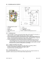
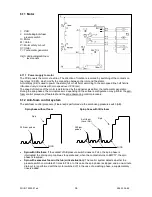
6.6.1 Calculation of flow rate
Calculation of the capacity – necessary to determine the time for the supplementary fill – is performed by
measuring the time that elapses between the closure of the anti-boiling contact on FULL and the closure of
the 1st level contact.
Volume
Flow rate
=
Time (T1-T2)
Volume
= Volume of the tub between the two levels (anti-boiling and 1st level)
T1 –T2 =
The time that elapses between the closure of the anti-boiling and 1st level contacts on FULL.
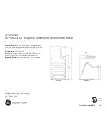
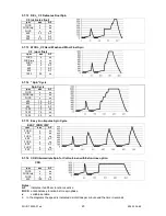
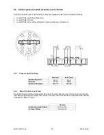
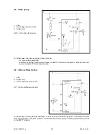
Water fill diagram
ELT =
solenoid valve
P1
= 1st level
AB
= anti-boiling level
rpm
= drum rotation speed
Water in
= water fill
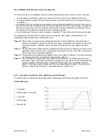
Phase A:
The phase during which the initial fill takes place:
1. Water fill until the anti-boiling pressure switch closes on FULL.
2. Water fill until the 1st level pressure switch closes on FULL: the delivery of the solenoid is
calculated during this phase.
3. Water fill for time
Q
, which varies according to delivery and cycle phase.
Phase B:
If the 1st level pressure switch returns to EMPTY, a supplementary fill is performed until the
pressure switch returns to close on FULL. This phase may be followed by a further timer-
controlled fill.