SOI/DT 2002-07 eb
36
599 35 36-69
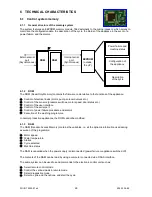
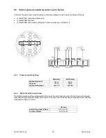
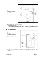
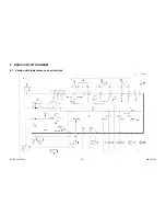
6.11 Motor
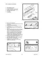
1. PCB
2. Anti-boiling/anti-foam
pressure switch
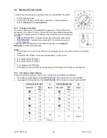
13. Motor
M = Rotor
P = Motor safety cut-out
S = Stator
T = Tachometric generator
AB_S Anti-boiling/anti-foam
level sensor
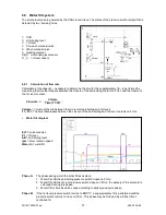
6.11.1 Power supply to motor
The PCB powers the motor via a triac. The direction of rotation is reversed by switching of the contacts on
two relays (K2-K3), which modify the connection between the rotor and the stator.
A third relay (K4) is used to power the stator (full or half field) according to the spin speed
(the half field is
introduced only in models with spin speed over 1200 rpm)
.
The speed of rotation of the motor is determined by the signal received from the tachometric generator.
During the spin phases, the microprocessor, depending on the software configuration, may perform the anti-
foam control procedure (if featured) and the anti-unbalancing control procedure.
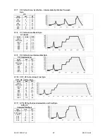
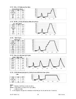
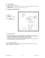
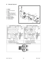
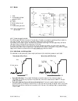
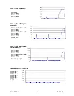
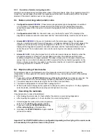
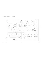
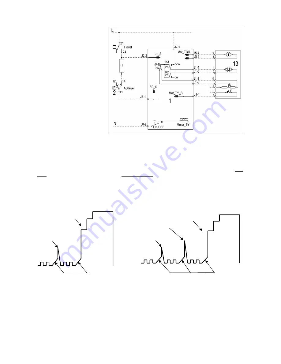
6.12 Anti-foam control system
The anti-foam control procedure (if featured) is performed via the anti-boiling pressure switch (AB).
Spin phase without foam
Spin phase with little foam
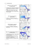
•
Spin with little foam:
if the contact of AB pressure switch closes on FULL, the spin phase is
interrupted; the drain pump continues to operate and, when the contact returns to EMPTY, the spin
phase is resumed.
•
Spin with excessive foam in the tub (critical situation):
The control system detects whether the
pressure switch commutates 5 times to FULL. In this case, the spin phase is skipped, and a one-minute
drain cycle is performed with the motor switched off; in the case of a washing phase, a supplementary
rinse is added.
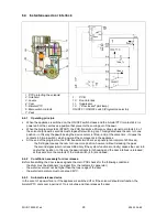
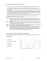
FUCS
300 rpm pulses
Spin
Anti-foam
( Level AB )
300 rpm
pulses
FUCS
Spin


