Guide to diagnostics of electronic controls EWM10931
2011 SOE/DT-mdm FCPD-dp Quality-tb
32/75
599 73 77-37
Checks to perform:
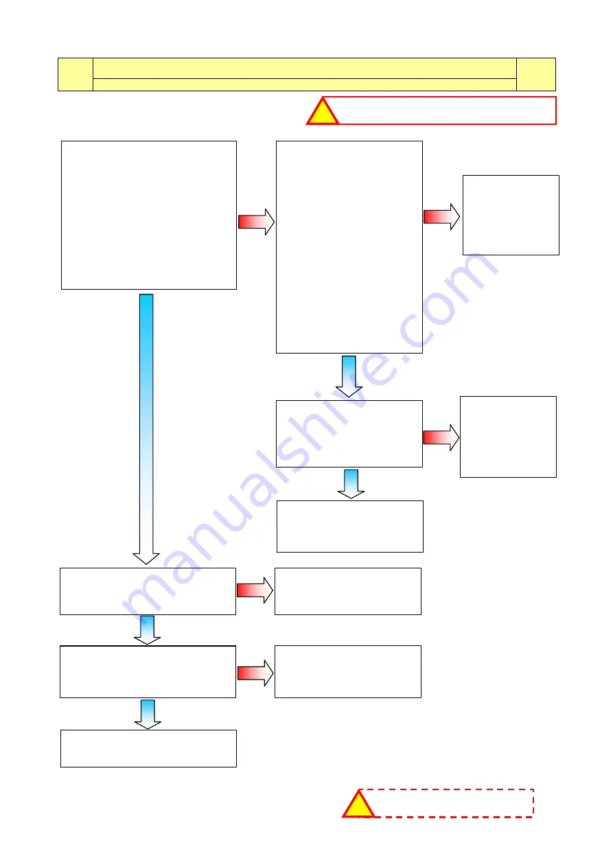
E41: Door open (device with 4 connections)
E41
Maximum time exceeded (5 pulses per instant)
E41
Disconnect the door lock
connectors and measure on
the component:
- between connectors 3 and
4, the circuit must NOT be
open (measure the
resistance value of the PTC).
- between connectors 2 and
4, the circuit must NOT be
open (measure the
resistance value of the PTC).
- on the other hand, between
connectors 4 and 5, the
circuit must be OPEN
(the numbers are printed on
the component).
Is the door lock ok?
-(fig.9)-
To check the wiring, measure, with
the door open, between the
following wiring connectors
-(fig.4)-
:
- between J5-1 and J5-3, the circuit
must NOT be open (measure the
resistance value of the PTC).
- between J5-1 and J5-4, the circuit
must NOT be open (measure the
resistance value of the PTC).
- between wire J5-1 and J5-2, the
circuit must be OPEN.
Is the system ok?
Replace the door
lock and repeat
the diagnostic
cycle to check
for any
further alarms.
Replace the door lock.
Is the appliance
working correctly?
Check the mechanical coupling
between the door lock and the door
latch. Is the system efficient?
Replace the door
latch/the door.
Replace the circuit board
and repeat the diagnostic
cycle to check for any
further alarms.
Repeat the diagnostic cycle to
check for any further alarms.
Measure the continuity
between connector J5
(main circuit board) and
the door lock connector.
Is the wiring ok?
Replace the
wiring and repeat
the diagnostic
cycle to check
for any
further alarms.
Replace the circuit board
and repeat the diagnostic
cycle to check for any
further alarms.
If there are burns on the circuit
board, see page 73
!
NO
NO
NO
NO
NO
Y
E
S
Y
E
S
Y
E
S
Y
E
S
Y
E
S
Check that all the connectors are correctly inserted
!