background image

���������� �������

�������� �������

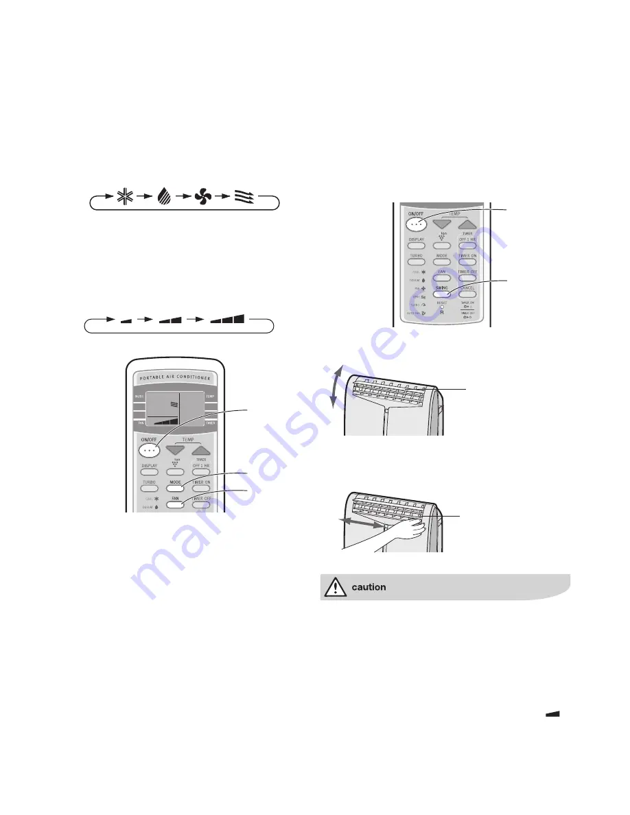
Ventilation mode

In this mode, the air conditioner ventilates the air  

to outdoors

Install the exhaust hose (See Page 7-8), turn the drainage 

nozzle to the CLOSE position, and check the drainage 

nozzle is covered with the stopcock (upper).

1.  Press the MODE button to select VENT mode.

.  Press the ON/OFF button to start operation.

  • The red OPERATION lamp on the unit will illuminate.

  • The temperature cannot be set.

3.  Press the FAN button to set the desired fan speed.

  •  Although the louvres are closed and no air blows 

out into the room, the external ventilation fan speed 

changes.

To turn off

Press the ON/OFF button again.

• The red OPERATION lamp on the unit will turn off.

COOL

DEHUM

FAN

VENT

COOL

DEHUM

FAN

VENT

COOL DEHUM

FAN

VENT

COOL DEHUM

FAN

VENT

QUIET LOW

HIGH

1

3

2

1

3

2

To change air flow direction

Up/down air flow direction

1.  Press the ON/OFF button to start operation.

  • The red OPERATION lamp on the unit will illuminate.

.  Press the SWING button on the remote control.

  • The horizontal louvres will swing continuously.

3.   Press the SWING button again when the horizontal 

louvres are at the desired position.

  • The horizontal louvres will stop moving.

  •  The adjusted position will be memorized and the same 

position will be set automatically when operated the 

next time.

NOTE

•  During VENTILATION mode, UP/DOWN air flow direction 

cannot be changed.

Left/right air flow direction

Hold the vertical louvre as shown in the diagram below and 

adjust the air flow direction.

Never attempt to adjust the horizontal louvres manually.

•   Manual adjustment of the horizontal louvres can cause 

the unit to malfunction when the remote control is used 

for adjustment.

• When the horizontal louvres are positioned at the  


lowest position in the COOL or DEHUMIDIFICATION

  mode for an extended period of time, condensation  

may result.

Do not adjust the vertical louvres to the extreme left or right 

in the COOL mode with the fan speed set to “QUIET (

���������� �������

�������� �������

)” 

for an extended period of time.

Condensation may form on the louvres.

���������� �������

�������� �������

���������� �������

�������� �������


electrolux EXP09CS1WI 

ventilation mode/air flow direction 15

Summary of Contents for EXP09CS1WI

Page 1: ... of our products We devote time knowledge and a great deal of thought to anticipating and creating the kind of appliances that our customers really need and want This kind of thoughtful care means innovating with insight Not design for design s sake but design for the user s sake For us thoughtful design means making appliances easier to use and tasks more enjoyable to perform freeing our customer...

Page 2: ...FAN Button 11 TIMER OFF Button 12 CANCEL Button 13 SWING Button 14 RESET Button 15 TURBO Cool Button 16 MODE SYMBOLS COOL DEHUMIDIFICATION FAN VENTILATION 17 TURBO COOL SYMBOL 18 PLASMACLUSTER SYMBOL 19 FAN SPEED SYMBOLS AUTO Manual setting 20 TEMPERATURE AND TIMER COUNT DOWN INDICATOR 21 TRANSMITTING SYMBOL 22 TIMER ON TIMER OFF SYMBOL 1 2 3 4 5 6 7 8 9 10 11 12 13 14 15 16 17 18 19 20 21 22 1 Tr...

Page 3: ...nd hazards For future reference please store this manual in a safe place Contents Important safety instructions 2 Operating conditions 5 Included 5 Using the remote control 6 Installation and removal of exhaust hose 7 Installation of window kit 9 Cool mode 13 Dehumidification mode 13 Fan mode 14 Ventilation mode 15 To change air flow direction 15 Turbo cool operation 16 Off 1 hr timer 16 Timer ope...

Page 4: ...asure in the future The Electrolux ambition is to offer a wide variety of quality products that make your life more comfortable You find some examples on the cover in this manual Please take a few minutes to study this manual so that you can take advantage of the benefits of your new machine We promise that it will provide a superior User Experience delivering Ease of Mind Good luck ...

Page 5: ...or damage to property Meanings of symbols used in this manual are shown below This symbol indicates never to do this This symbol indicates always do this Important safety instructions important safety instructions electrolux EXP09CS1WI warning warning meaning Plug in power plug properly Otherwise it may cause electric shock or fire due to excess heat generation Do not operate or stop the unit by i...

Page 6: ... of indoor and soaking of household furniture Hold the plug by the head of the power plug when taking it out It may cause electric shock and damage Turn off the main power switch when not using the unit for a long time It may cause failure of product or fire caution meaning Do not place obstacles around air inlets or inside of air outlet It may cause failure of appliance or accident Always insert ...

Page 7: ...hose must have no kinks and must not be elevated during dehumidification mode If not the drained water may spill out into the room The temperature around the drainage hose must not be below freezing point when used Drained water may freeze inside the hose causing water inside the unit to overflow into the room Do not block the exhaust air outlet with obstacles Cooling performance may be reduced or...

Page 8: ...the running costs Location The air conditioner should be placed on a firm foundation to minimize noise and vibration For safe and secure positioning place the unit on a smooth level floor strong enough to support the unit The unit has casters to aid placement but it should only be rolled on smooth flat surfaces Use caution when rolling on carpet surfaces Do not attempt to roll the unit over object...

Page 9: ...ts signal receiver window and press the desired button A beep will sound when the unit receives the signal Make sure nothing such as curtains block the signal receiver window The remote control operates up to 7 meters away Do not expose the signal receiver window to direct sunlight This may adversely affect its operation If necessary close curtains to block out the sunlight Use of a fluorescent la...

Page 10: ...dapter and turn it approx three times until it stops Make sure they are securely attached afterwards 3 Attach the exhaust hose adapter to the unit Insert the two projections on the exhaust hose adapter into the two holes on the unit and firmly attach them to each other Installation and removal of exhaust hose Installation without window kit The exhaust hose should be as short as possible for opera...

Page 11: ...el and attach the window exhaust adapter Surface of window exhaust adapter marked TOP should be at the top when it is installed in a doublehung sash window Surface of window exhaust adapter marked TOP should be on the window frame side when it is installed in a sliding sash window Installation and removal of exhaust hose Installation only together with window kit The exhaust hose should be as shor...

Page 12: ...t the foam seal A adhesive type to the proper length and attach it to the window sill 4 Attach the window panel to the window sill A If the inner width of the window is between 559mm and 609mm inclusive The window panel cannot be installed in windows less than 559mm wide as you will be unable to shut the exhaust cover In such cases the exhaust cover will have to be removed prior to installing the ...

Page 13: ...e window sash and place the window panel on the window stool Slide the adjustment and extension panels to fit the window frame width Secure the window panel to the window stool with 4 screws 5 Cut the foam seals A and B adhesive type to the proper length and attach it to the window panel Attach foam seal A to the window panel and extension panel and attach foam seal B to the adjustment panel 6 Clo...

Page 14: ...seal A adhesive type to the proper length and attach it to the window frame 4 Install the window panel into the window frame A If the inner height of the window is between 559mm and 609mm inclusive The window panel cannot be installed in windows less than 559mm high as you will be unable to shut the exhaust cover In such cases the exhaust cover will have to be removed prior to installing the windo...

Page 15: ... stool Slide the adjustment and extension panels to fit the window frame width Secure the window panel to the window stool with 4 screws 5 Cut the foam seals A and B adhesive type to the proper length and attach it to the window panel Attach foam seal A to the window panel and extension panel and attach foam seal B to the adjustment panel 6 Close the window sash securely against the window panel 7...

Page 16: ...ned off Drain water will squirt out if attempted during operation 4 Insert the hose clamp into a standard commercially available hose 12 7mm inner diameter 16 7mm outer diameter 5 Attach the hose to the drainage nozzle and secure it with the hose clamp Depending on room condition approximately 28 litres of water per day 24 hours will be dehumidified Prepare some kind of bucket of appropriate size ...

Page 17: ...g without the exhaust hose Dehumidification mode cont COOL DEHUM FAN VENT COOL DEHUM FAN VENT COOL DEHUM FAN VENT COOL DEHUM FAN VENT Hose clamp Drain hose COOL OPEN position DEHUM FAN VENT 7 6 Fan mode In this mode the air conditioner simply circulates the air without cooling it Turn the drainage nozzle to the CLOSE position and check the drainage nozzle is covered with the stopcock 1 Press the M...

Page 18: ... the SWING button on the remote control The horizontal louvres will swing continuously 3 Press the SWING button again when the horizontal louvres are at the desired position The horizontal louvres will stop moving The adjusted position will be memorized and the same position will be set automatically when operated the next time NOTE During VENTILATION mode UP DOWN air flow direction cannot be chan...

Page 19: ...FF 1 HR TIMER is set the unit will automatically turn off after one hour 1 Press the OFF 1HR button The remote control displays The orange TIMER lamp on the unit will illuminate The unit will stop operating after one hour To cancel Press the CANCEL button The orange TIMER lamp on the unit will turn off Alternatively turn the unit off by pressing the ON OFF button The red OPERATION lamp and the ora...

Page 20: ... will be cancelled If a power failure occurs while the TIMER OFF or TIMER ON is set the TIMER setting will be cancelled and will not be retrieved even after the power is restored 0 5h 1 0h 1 5h 10h 11h 12h 1 0 5h 1 0h 1 5h 10h 11h 12h 1 Timer on The unit will turn on automatically according to your setting Timer duration can be set from a minimum of half an hour 30 minutes to a maximum of 12 hours...

Page 21: ... DISPLAY button PLASMACLUSTER operation cannot be set during VENTILATION mode Plasmacluster operation Use this mode when the remote control is not available 1 Press the MANUAL button on the unit The red OPERATION lamp on the unit will illuminate If the unit has not been unplugged since its last operation it will resume operation at its last settings If the unit has been unplugged since its last op...

Page 22: ...r future use 9 Turn the drainage nozzle to the CLOSE position Drainage Stopcock Receptacle not supplied Drainpipe nozzle Drainage nozzle Stopcock Upper OPEN position Hose clamp Drain hose Stopcock Drainage nozzle Stopcock Upper OPEN position Hose clamp Drain hose Whenever the unit is moved to prevent water within the unit from spilling When the unit is not going to be used for a long time 1 Carry ...

Page 23: ... a soft dry cloth or with a cloth moistened with a mild soap Carefully remove any residue by wiping with a damp cloth and dry completely Avoid splashing water onto the unit Water can dangerously damage the electrical insulation Never use harsh chemicals or abrasive cleaners on any part of the unit To avoid damaging the unit do not use hot water not greater than 50 C when cleaning Cleaning the inse...

Page 24: ...y normal A soft swishing noise can be heard immediately after the unit is turned on or off and also during operation This is the sound of the refrigerant flowing inside the unit A low buzzing noise is emitted when the unit is generating Plasmacluster ions This air conditioner evaporates water condensed during cooling operation within the unit through the exhaust air outlet Although a water flowing...

Page 25: ... ensure you have read the details under the heading Something not working When you contact the Service Force Centre you will need to give the following details 1 Your name address and postcode 2 Your telephone number 3 Clear concise details of the fault 4 The model and Serial number of the appliance found on the rating plate 5 The purchase date Please note a valid purchase receipt or guarantee doc...

Page 26: ...electrolux EXP09CS1WI front rear view 23 ...

Page 27: ...24 operating conditions energy tips inclusions electrolux EXP09CS1WI ...

Reviews: