background image





4-

31

32

-

40

41

-

4

7

4

8

-

5

8

5

9

-

6

1

2007 Room Air Conditioners

FACTORY LOCATION I
LOCATED AS FIRST DIGIT

IN SERIAL NUMBER

Summary of Contents for FAA055P7A-1

Page 1: ... 4 31 32 40 41 47 48 58 59 61 2007 Room Air Conditioners FACTORY LOCATION I LOCATED AS FIRST DIGIT IN SERIAL NUMBER ...

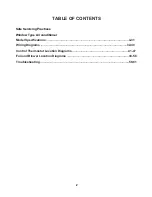
Page 2: ...NTENTS Safe Servicing Practices Window Type Air conditioner Model Specifications 4 31 Wiring Diagrams 32 40 Control Thermostat Location Diagrams 41 47 Fan and Blower Location Diagrams 48 58 2 Troubleshooting 59 61 ...

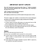
Page 3: ...ave TWO buttons on the plug head Press the TEST button You will notice a click as the RESET button pops out 3 Press the RESET button Again you will notice a click as the button engages 4 The power supply cord is now supplying electricity to the unit On some products this is also indicated by a light on the plug head Notes Do not use this device to turn the unit on or off Always make sure the RESET...

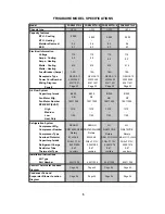
Page 4: ...vaporator Blower Location FAX050P7A 4 5 000 0 4 9 7 115 5 2 515 15A Page 32 1370 1150 LG QA075CDE MRA12112 12026 OPP5 40020558 63611621 NEMA5 15 35 8uF 370V 8 250 15011035 KB 03001274 9 87 03001274 9 87 capillary capillary 03001280 9 87 03001280 9 87 capillary capillary Rotary 64611008 64611008 64611008 64611008 FAX050P7A 5 5 000 0 4 9 7 115 5 2 515 15A Page 32 1370 1150 LG QA075CDE MRA12112 12026...

Page 5: ...vaporator Blower Location KB 03001280 9 87 capillary 03001280 9 87 capillary 03001274 9 87 capillary 03001274 9 87 capillary 64611008 64611008 64611008 64611008 NF KB NF FAX052P7A 4 0 4 9 7 5 2 515 1370 1150 LG OPP5 40020558 63611621 35 8uF 370V 15011035 8 250 5 000 115 15A Page 32 Rotary NEMA5 15 MRA12112 12026 QA075CDE FAX052P7A 5 0 4 9 7 5 2 515 1370 1150 LG OPP5 40020558 63611621 35 8uF 370V 1...

Page 6: ...ower Location 03001280 9 87 Electronic 64611008 KB NF KB NF FAX054P7A 1 40020558 0 4 9 7 5 2 515 1370 1270 1150 SENLIN BF900 KB 63611326 35 8uF 370V 15011035 8 250 5 000 115 15A Page 32 Rotary NEMA5 15 OPP5 SD074SW H3BD 03001280 9 87 03001274 9 87 03001274 9 87 Electronic 64611008 64611008 64611008 FAX054P7A 2 40020558 0 4 9 7 5 2 515 1370 1270 1150 SENLIN BF900 KB 63611326 35 8uF 370V 15011035 8 ...

Page 7: ...am Control Thermostat Location Diagram Condenser Fan and Evaporator Blower Location MS 2 4002057201 63611618 NEMA5 15 35uF 6uF 300V 6 250 150110362 1100 970 850 Rotary 64611007 7 FAA055P7A 1 5 200 11 115 0 6 4 9 475 15A Page 33 SENLIN SD074UW H3BG BF900 KB MS 2 4002057201 63611618 NEMA5 15 35uF 6uF 300V 6 250 KB KB 1100 970 850 Rotary 64611007 150110362 FAA055P7A 2 5 200 11 115 0 6 4 9 475 15A Pag...

Page 8: ...Blower Location FAA060P7A 4 LG MRA98703 790 MS 2 4002057201 35uF 6uF 300V 6 250 6 000 0 6 9 7 115 6 620 15A Page 33 1100 970 850 QA084CAF Rotary 63611620 NEMA5 15 64611007 150110362 FAA060P7A 5 LG MRA98703 790 MS 2 4002057201 35uF 6uF 300V 6 250 6 000 0 6 9 7 115 6 620 15A Page 33 1100 970 850 QA084CAF Rotary 63611620 NEMA5 15 64611007 150110362 FAA060P7A 1 SENLIN BF900 KB MS 2 4002057201 35uF 6uF...

Page 9: ...Blower Location FAA062P7A 1 MS 2 6 250 SENLIN BF900 KB 4002057201 35uF 6uF 300V KB 6 000 0 6 9 7 115 6 620 15A Page 33 1100 970 850 Rotary 63611620 NEMA5 15 03001050 10 2 03001050 10 2 03001276 10 2 03001276 10 2 Capillary Capillary Capillary Capillary 64611007 SD086SW H3BG 150110362 FAA062P7A 2 MS 2 6 250 SENLIN BF900 KB 4002057201 35uF 6uF 300V NF 6 000 0 6 9 7 115 6 620 15A Page 33 1100 970 850...

Page 10: ...ocation FAA065P7A 1 MS 2 1100 970 850 SENLIN BF900 KB 4002057201 35uF 6uF 300V KB 6 000 0 6 10 7 115 5 5 560 15A Page 33 Rotary 63611618 NEMA5 15 SD086UW H3BG 6 250 150110362 FAA065P7A 2 MS 2 1100 970 850 SENLIN BF900 KB 4002057201 35uF 6uF 300V NF KB NF 6 000 0 6 10 7 115 5 5 560 15A Page 33 Rotary 63611618 NEMA5 15 SD086UW H3BG 6 250 150110362 FAA065P7A 4 MS 2 1100 970 850 LG MRA98703 790 400205...

Page 11: ...on 11 FAA067P7A 4 15A Page 34 LG QA084CAF MRA12112 790 MS 2 4002057201 63611619 NEMA5 15 35uF 6uF 300V 6 250 150110362 KB 1100 970 850 Rotary 6 000 0 6 10 7 115 5 5 560 64611007 FAA067P7A 5 15A Page 34 LG QA084CAF MRA12112 790 MS 2 4002057201 63611619 NEMA5 15 35uF 6uF 300V 6 250 150110362 NF 1100 970 850 Rotary 6 000 0 6 10 7 115 5 5 560 64611007 FAA067P7A 1 15A Page 34 SENLIN SD086UW H3BG BF900 ...

Page 12: ...82P7A 1 MS 2 15 250 4002057201 35 15uF 370V KB 8 000 0 8 9 8 115 7 6 815 15A Page 33 1480 1380 1280 2R11S126A6H Rotary 63611620 NEMA5 15 15011036 19 75 19 75 19 75 19 75 MATSUSHITA WANBAO MRA98076 64611007 FAA082P7A 2 MS 2 15 250 4002057201 35 15uF 370V NF 8 000 0 8 9 8 115 7 6 815 15A Page 33 1480 1380 1280 2R11S126A6H Rotary 63611620 NEMA5 15 15011036 MATSUSHITA WANBAO MRA98076 64611007 FAA082P7...

Page 13: ...19 75 19 75 19 75 Capillary Capillary Capillary Capillary FAA084P7A 1 MS 2 15 250 8 000 0 8 9 8 115 7 6 815 1480 1380 1280 MRA98076 4002057201 35 15uF 370V KB 15A Page 33 Rotary 63611618 NEMA5 15 15011036 64611007 MATSUSHITA WANBAO 2R11S126A6H FAA084P7A 2 MS 2 15 250 8 000 0 8 9 8 115 7 6 815 1480 1380 1280 MRA98076 4002057201 35 15uF 370V NF 15A Page 33 Rotary 63611618 NEMA5 15 15011036 64611007 ...

Page 14: ...A 4 MS 2 8 000 0 8 10 8 115 15 740 NEMA 5 15 4002057201 63611618 Page 33 KB 15011036 1480 1380 1280 MATSUSHITA WANBAO 15A 15 250 FAA085P7A 1 MS 2 8 000 0 8 10 8 115 15 740 NEMA 5 15 4002057201 63611618 Page 33 35 15μF 370V KB 15011036 1480 1380 1280 2R11S126A6H Rotary MRA98076 19 75 03001290 15A 15 250 Electronic MATSUSHITA WANBAO 35 15μF 370V 2R11S126A6H Rotary MRA98076 19 75 03001288 Electronic ...

Page 15: ...A 1 FAA087P7A 4 15A Page 34 MRA98073 12026 MS 2 MS 2 4002057201 4002057201 63611619 NEMA5 15 NEMA5 15 NEMA5 15 NEMA5 15 40 15uF 370V 15 250 15 250 15011036 KB 18 34 03001275 115 15A Page 34 Rotary Rotary 63611619 15011036 20 45 03001047 Electronic LG 8 000 0 8 10 8 8 000 0 8 10 8 115 740 7 1 740 7 1 1480 1380 1280 1480 1380 1280 QA104CCA FAA087P7A 2 FAA087P7A 5 15A Page 34 2R11S126A6H MS 2 MS 2 40...

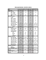
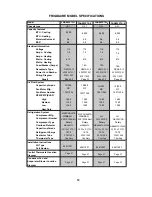
Page 16: ...70V 40 15uF 370V 22 92 03001040 22 92 Capillary Electronic MRA99111 9200 64511018 16 FAC102P1A 3 Power Cord Number Page Page 34 High Medium Low Heat Only SANYO SANYO C 1RE142H02AA FRIGIDAIRE MODEL SPECIFICATIONS Model Chassis type Capacity features BTU Cooling BTU Heating Moisture Removal EER Electrical Information Voltage Amps Cooling Amps Heating Watts Cooling Watts Heating Fuse Breaker Amps Rec...

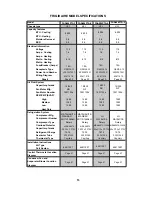
Page 17: ...on Diagram Condenser Fan and Evaporator Blower Location COM II COM II 4002057202 4002057202 63611618 63611618 50 15uF 370V 29 98 03001042 10 000 10 000 1 4 10 8 10 8 115 9 7 925 925 Page 33 1460 1350 1240 Rotary Rotary MRA99111 9200 MRA12061 12026 40 15uF 370V 30 33 03001057 15 250 15011037 NT 15 250 15011037 DY FAC105P1A 2 COM II 4002057202 10 000 1 4 10 8 115 9 7 925 Page 33 1460 1350 1240 15 25...

Page 18: ...fg Refrigeration System Compressor Mfg Compressor Number Compressor Type Part Number Overload Protector Capacitor µ farads Refrigerant Charge Restrictor Tube Thermostat Type Installation Instructions Kit Type Diagram Control Thermostat Location Diagram Condenser Fan and Evaporator Blower Location COM II 50 15uF 370V 15 250 15011037 NT 29 98 03001042 Rotary 4002057202 63611618 FAC106P1A 4 10 000 1 ...

Page 19: ... Information Voltage Amps Cooling Amps Heating Watts Cooling Watts Heating Fuse Breaker Amps Receptacle Type Wiring Diagram Fan Motor Number RPM CMP EVAP Air Flow System Capacitor µ farads Fan Motor Mfg Refrigeration System Compressor Mfg Compressor Number Compressor Type Part Number Overload Protector Capacitor µ farads Refrigerant Charge Restrictor Tube Thermostat Type Installation Instructions ...

Page 20: ...AP Air Flow System Capacitor µ farads Fan Motor Mfg Refrigeration System Compressor Mfg Compressor Number Compressor Type Part Number Overload Protector Capacitor µ farads Refrigerant Charge Restrictor Tube Thermostat Type Installation Instructions Kit Type Diagram Control Thermostat Location Diagram Condenser Fan and Evaporator Blower Location COM II 40 15uF 370V 15 250 15011037 NT 30 33 03001057...

Page 21: ...02 63611619 60 15uF 370V 31 75 03001043 FAC127P1A 1 Page 34 LG B405 150 241A MRA12061 12026 FRIGIDAIRE MODEL SPECIFICATIONS Model Chassis type Capacity features BTU Cooling BTU Heating Moisture Removal EER Electrical Information Voltage Amps Cooling Amps Heating Watts Cooling Watts Heating Fuse Breaker Amps Receptacle Type Wiring Diagram Fan Motor Number RPM CMP EVAP Air Flow System Capacitor µ fa...

Page 22: ...load Protector Capacitor µ farads Refrigerant Charge Restrictor Tube Thermostat Type Installation Instructions Kit Type Diagram Control Thermostat Location Diagram Condenser Fan and Evaporator Blower Location FAM156R1A 2 MED 15100 1 8 10 7 115 15 1410 NEMA 5 15 4002057202 63611613 Page 34 45 370 DY 15011038 1030 940 850 Matsushita 2P20S3R126B1C Rotary MRA98896 9200 44 44 03001048 15A 15 370 Electr...

Page 23: ...load Protector Capacitor µ farads Refrigerant Charge Restrictor Tube Thermostat Type Installation Instructions Kit Type Diagram Control Thermostat Location Diagram Condenser Fan and Evaporator Blower Location FAM157R1A 2 MED 15100 1 8 10 7 115 15 1410 NEMA 5 15 4002057202 63611329 Page 35 45 370 DY 15011038 1030 940 850 Matsushita 2P20S3R126B1C Rotary MRA98896 9200 44 44 03001048 15A 15 370 Electr...

Page 24: ...ation Diagram Condenser Fan and Evaporator Blower Location FAM186R2A 1 MED 18 500 18 200 2 6 9 7 230 208V 15 1 730 1 700 NEMA 6 15 40020559 63611613 Page 34 35 450 DY 150110381 1080 1000 950 LG QJ250KBE Rotary MRA12107 12027 B273 150 141E 38 8 03001051 15A 8 450 Electronic FAM18ER2A 1 MED 18 500 18 200 16 000 13 000 2 6 9 7 230 208V 15 1 900 1 880 NEMA 6 15 40020560 63611628 Page 39 35 450 DY 1501...

Page 25: ...RE MODEL SPECIFICATIONS 25 Model Chassis type Capacity features BTU Cooling BTU Heating Moisture Removal EER Electrical Information Voltage Amps Cooling Amps Heating Watts Cooling Watts Heating Fuse Breaker Amps Receptacle Type Wiring Diagram Fan Motor Number RPM CMP EVAP Air Flow System Capacitor µ farads Fan Motor Mfg Refrigeration System Compressor Mfg Compressor Number Compressor Type Part Num...

Page 26: ...ures BTU Cooling BTU Heating Moisture Removal EER Electrical Information Voltage Amps Cooling Amps Heating Watts Cooling Watts Heating Fuse Breaker Amps Receptacle Type Wiring Diagram Fan Motor Number RPM CMP EVAP Air Flow System Capacitor µ farads Fan Motor Mfg Refrigeration System Compressor Mfg Compressor Number Compressor Type Part Number Overload Protector Capacitor µ farads Refrigerant Charg...

Page 27: ...s Receptacle Type Wiring Diagram Fan Motor Number RPM CMP EVAP Air Flow System Capacitor µ farads Fan Motor Mfg Refrigeration System Compressor Mfg Compressor Number Compressor Type Part Number Overload Protector Capacitor µ farads Refrigerant Charge Restrictor Tube Thermostat Type Installation Instructions Kit Type Diagram Control Thermostat Location Diagram Condenser Fan and Evaporator Blower Lo...

Page 28: ...R Electrical Information Voltage Amps Cooling Amps Heating Watts Cooling Watts Heating Fuse Breaker Amps Receptacle Type Wiring Diagram Fan Motor Number RPM CMP EVAP Air Flow System Capacitor µ farads Fan Motor Mfg Refrigeration System Compressor Mfg Compressor Number Compressor Type Part Number Overload Protector Capacitor µ farads Refrigerant Charge Restrictor Tube Thermostat Type Installation I...

Page 29: ...d Evaporator Blower Location Diagram Kit Type Part Number Control Thermostat Location Diagram Refrigerant Charge Restrictor Tube Thermostat Type Installation Instructions Compressor Number Compressor Type Overload Protector Capacitor µ farads Fan Motor Number RPM CMP EVAP Refrigeration System Compressor Mfg Wiring Diagram Air Flow System Capacitor µ farads Fan Motor Mfg Watts Cooling Watts Heating...

Page 30: ...310 1310 Low 1210 1210 Heat Only Hitachi Shanghai Hitachi Shanghai SL193SN C7LU SL193SN C7LU Rotary Rotary 40 450 40 450 23 52 23 52 03001272 03001272 30 Condenser Fan and Evaporator Blower Location Diagram Kit Type Part Number Control Thermostat Location Diagram Refrigerant Charge Restrictor Tube Thermostat Type Installation Instructions Compressor Number Compressor Type Overload Protector Capaci...

Page 31: ...Capacitor µ farads Refrigerant Charge Restrictor Tube Thermostat Type Installation Instructions Kit Type Diagram Control Thermostat Location Diagram Condenser Fan and Evaporator Blower Location 15A 15A 8 450 15 250 Electronic 10 1320 1220 1120 NEMA5 15 Electronic 64511094 64511094 FAK105R7V 2 FAK124R1V 1 FAK124R1V 2 S C S C S C 10000 12000 12000 1 5 1 6 1 6 9 47 9 48 9 48 115 115 115 7 2 10 1050 1...

Page 32: ...32 63611621 63611326 ...

Page 33: ...33 63611618 63611620 ...

Page 34: ...34 63611619 M1 M2 63611613 ...

Page 35: ...35 63611329 63611614 ...

Page 36: ...36 633611615 63611622 ...

Page 37: ...37 63611616 63611091 ...

Page 38: ...38 63611642 ...

Page 39: ...39 63611328 ...

Page 40: ...40 63611094 63611629 ...

Page 41: ...Control Thermostat Location diagram for Heavy Duty 41 ...

Page 42: ...Control Thermostat Location diagram for Median 42 ...

Page 43: ...Control Thermostat Location diagram for Slider Casement 43 ...

Page 44: ...Control Thermostat Location diagram for TTW 44 ...

Page 45: ...The 5th pipe The 4th pipe 160cm Control Thermostat Location diagram for COM2 45 ...

Page 46: ...The 5th pipe The 4th pipe 130cm Control Thermostat Location diagram for OPP5 46 ...

Page 47: ...The 5th pipe The 4th pipe 160cm Control Thermostat Location diagram for MS2 47 ...

Page 48: ...Condenser Fan and Evaporator Blower Location Diagram for TTW 1 48 ...

Page 49: ...Condenser Fan and Evaporator Blower Location Diagram for Slider Casement 1 49 ...

Page 50: ...Condenser Fan and Evaporator Blower Location Diagram for Heavy Duty 1 50 ...

Page 51: ...Condenser Fan and Evaporator Blower Location Diagram for Median 1 51 ...

Page 52: ...Condenser Fan and Evaporator Blower Location Diagram for TTW 2 52 ...

Page 53: ...Condenser Fan and Evaporator Blower Location Diagram for Slider Casement 2 53 ...

Page 54: ...Condenser Fan and Evaporator Blower Location Diagram for Median 2 54 ...

Page 55: ...Condenser Fan and Evaporator Blower Location Diagram for Heavy Duty 2 55 ...

Page 56: ...Condenser Fan and Evaporator Blower Location Diagram for OPP5 56 ...

Page 57: ...Condenser Fan and Evaporator Blower Location Diagram for MS2 57 ...

Page 58: ...Condenser Fan and Evaporator Blower Location Diagram for COM2 58 6cm 8cm ...

Page 59: ... the electronic control DO NOT assume a service problem is directly caused by the electronic control system A line voltage component including power cord and wiring that has opened shorted groundedorotherwisemalfunctioned mayhavecreated a service problem Low voltage can also be the direct result of inadequately wired circuits extension cords or loose fuses and connections to the power supply Volta...

Page 60: ...motor 5 Condenser air flow restriction 6 Condenser fins damanged 7 Capacitor 8 Wiring 9 Refrigerant system Insufficient cooling 1 Low capacity 2 Air filter 3 Exhaust door open 4 Unit undersized Excessive noise 1 Evaporator blower wheel 2 Condenser wheel 3 Copper tubing 4 Compressor internal noise 5 Fan motor Excessive water or condensation 1 Unit operating under extremely high humidity conditions ...

Page 61: ... outside temperature No heat 1 No power 2 Selector switch position 3 Temperature control position 4 Fan motor 5 Heating element 6 Selector switch 7 Temperature control 8 Terminals and connectors Fan motor will not rotate during heat cycle 1 Thermostatic drain valve Water level control if Heat Cool models only applicable ...

Reviews: