2-15
Door Handle Mounting Instructions
For some installations the door handle may need to be
removed. (See Figure 2-30)
To remove the door handle:
1. Remove screw cover plates by pushing in and
sliding the screw cover plate off of the door handle.
2. Using a phillips head screwdriver, extract the screws
securing the door handle to the door assembly.
3. Push upwards until the screw button assembly is free
of the dovetail inside the handle assembly.
Care & Cleaning Of Your Trim Kit
The trim and grill kit surfaces are best cleaned with a
cotton cloth dampened with a mixture of water and mild
detergent. Avoid using abrasive cleaners as they will
mar the surface of the metal components.
Door Removal
For some installations it may be necessary to remove the
door to fit through the entrance of the installation site.
To remove the door, follow the steps below.
1. Make sure electrical plug is disconnected from the
wall outlet.
2. Gently lay freezer on its back on a soft clean
surface.
3. Lift plastic cover off upper hinge assembly.
(See Figure 2-28)
3. Using a 3/8” socket or wrench, extract the two bolts
securing the upper hinge to the unit frame.
4. Remove kickplate.
5. Using a 3/8” socket or wrench, extract the two bolts
securing the lower hinge to the unit frame. Use a
phillips head screwdriver to extract the remaining
screw from the lower hinge assembly.
(See Figure 2-29).
7. Lift the door assembly off of the unit frame.
Figure 2-28. Top Hinge Removal
Figure 2-29. Bottom Hinge Removal
Hinge Cover
3/8” Bolts
Hinge Plate
Section 2 Installation Information
Figure 2-30. Handle Removal
Set Screws
Summary of Contents for FPUH17D7KF All Freezer Professional Series
Page 2: ......
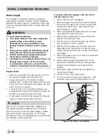
Page 20: ...Section 2 Installation Information 2 12 Figure 2 20 Figure 2 21 ...
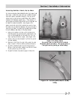
Page 21: ...Section 2 Installation Information 2 13 Figure 2 22 Figure 2 23 ...
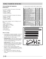
Page 24: ...Section 2 Installation Information 2 16 Notes ...
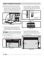
Page 26: ...Section 3 Electronic Control 3 2 Notes ...
Page 41: ...Section 4 Refrigeration 4 15 HFC 134a CFC 12 Pressure Temperature Chart ...
Page 44: ...Section 4 Refrigeration 4 18 Notes ...
Page 68: ...Section 6 Parts List 6 2 All Refrigerator Cabinet Exploded View And Parts List ...
Page 70: ...Section 6 Parts List 6 4 All Refrigerator Sealed System Exploded View And Parts List ...
Page 72: ...Section 6 Parts List 6 6 All Freezer Door Exploded View And Parts List ...
Page 74: ...Section 6 Parts List 6 8 All Freezer Cabinet Exploded View And Parts List ...
Page 76: ...Section 6 Parts List 6 10 All Freezer Sealed System Exploded View And Parts List ...
Page 78: ...Section 6 Parts List 6 12 Notes ...
Page 82: ...Section 7 Troubleshooting 7 4 Notes ...
Page 83: ...Section 8 Wiring Diagram 8 1 All Refrigerator Wiring Diagram ...
Page 84: ...8 2 Section 8 Wiring Diagram All Freezer Wiring Diagram ...

