Section 4 Refrigeration
4-10
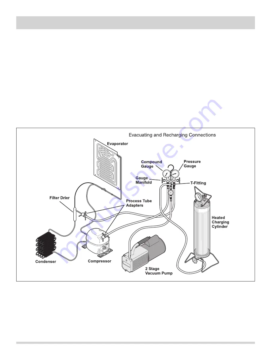
10. Slowly open the high-side manifold gauge valve
to allow the compressor to remove any refrigerant
trapped in the high-side hose and the process
fitting.
11. Close both of the manifold gauge valves. If the
high-side gauge reading rises, the pinch-off must be
corrected before proceeding.
12. Remove the high-side process tube adapter and
solder the process tube closed.
13. Clamp the low-side process tube with the pinch-off
tool while the unit is running. Remove the low-side
process tube adapter and solder the process tube
closed.
14. Check the process tubes for refrigerant leaks.
Final Leak Test
1. With the refrigerator/freezer turned OFF, leak test all
low-side system components.
2. Turn the unit ON and run until the condenser is
warm. Leak test the high-side system components.
Summary of Contents for FPUH17D7KF All Freezer Professional Series
Page 2: ......
Page 20: ...Section 2 Installation Information 2 12 Figure 2 20 Figure 2 21 ...
Page 21: ...Section 2 Installation Information 2 13 Figure 2 22 Figure 2 23 ...
Page 24: ...Section 2 Installation Information 2 16 Notes ...
Page 26: ...Section 3 Electronic Control 3 2 Notes ...
Page 41: ...Section 4 Refrigeration 4 15 HFC 134a CFC 12 Pressure Temperature Chart ...
Page 44: ...Section 4 Refrigeration 4 18 Notes ...
Page 68: ...Section 6 Parts List 6 2 All Refrigerator Cabinet Exploded View And Parts List ...
Page 70: ...Section 6 Parts List 6 4 All Refrigerator Sealed System Exploded View And Parts List ...
Page 72: ...Section 6 Parts List 6 6 All Freezer Door Exploded View And Parts List ...
Page 74: ...Section 6 Parts List 6 8 All Freezer Cabinet Exploded View And Parts List ...
Page 76: ...Section 6 Parts List 6 10 All Freezer Sealed System Exploded View And Parts List ...
Page 78: ...Section 6 Parts List 6 12 Notes ...
Page 82: ...Section 7 Troubleshooting 7 4 Notes ...
Page 83: ...Section 8 Wiring Diagram 8 1 All Refrigerator Wiring Diagram ...
Page 84: ...8 2 Section 8 Wiring Diagram All Freezer Wiring Diagram ...


