Section 6 Parts List
6-9
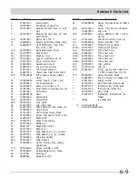
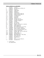
Ref # Part # Description
Ref # Part # Description
3
216503100
Screen-drain
5
297259600
Fan Blade, evaporator
6
297200600
Breaker Kit w/corners, no lock
slot
9
297200100
Breaker Kit w/corners, 32”, top
and bottom
13 #
297250000
Motor, fan, 115 V
14
216998100
Switch, light/lamp, black, ramp
15
216988100
Light Bulb/Lamp, long, blue
tint, 40 W, 120V
15A
297048600
Light Bulb/Lamp, short
16
241507803
Socket-light
16*
297109500
Washer, vinyl
16A
297139501
Socket, light/lamp, 25 W
18
216707200
Knob, temp control
19
216204902
Gasket-evap cover
20
216967200
Cover, temp control
21
216715200
Control-temperature
22
216823500
Clamp, cap tube, cold control
22A
5303916855 Tube, sensor sleeve, plastic,
clear
24
5304460604 Screw, type A, 10-24 x 3/8
25
297099253
Cover-evaporator
26
297248200
Ramp, door closer, LH
28
297283901
Hinge-bottom, stepped pin, LH
29
216313501
Hose-drain
32
5308005500 Drain
34
216816225
Shield-light
34A
297053102
Shield-light
34B
297053200
Lens, light
35
216273000
Clip, drain hose
37
241611303
Trim-cabinet corner, black, (2)
38
297283800
Hinge-upper
40
297164401
Cover-upper hinge, black
41
240578902
Screw, hex head, 1/4-20 x 5/8
42
216983102
Glass-shelf
42A
297007702
Glass-shelf, sliding
47
297192900
Baffle, air
50
08013207
Bracket-fan motor
59
297119000
Basket, (2)
60
297054200
Slide-basket, RH, (2), w/clips
60
297054201
Slide-basket, LH, (2), w/clips
60*
297049500
Clip-slide, basket
60A
297013500
Slide, basket
63
216396900
Screw, leveling foot, plastic,
adjustable
71A
297146800
Screw, 8-18AB x 0.470
72
297036901
Grille/Kickplate, 32”, black
79
3017666
Nut-insert
80
06594601
Bracket, control
93
5304460605 Screw, ph truss head, 8-18AB x
0.500
93A
297174300
Screw, #8, 18x.63, self pierce
*
216327800
Clip, wire
93B
216036601
Screw, RWHD, 8-32A x 0.500,
GX-CA
131
241513001
Channel-shelf mtg, side, (2)
132
5304460601 Screw, 6-20AB x 3/8
137
297050600
Frame-shelf, cantilever
137B 297007600
Frame-shelf, sliding
138
297050700
Trim-shelf, front
138A 216983601
Trim-shelf, side
138C 297007800
Trim-shelf, front
139
297050800
Trim-shelf, rear
139B 297007900
Trim-shelf, rear
154
297053000
Wire, jumper
155
5303313703 Clip, (2)
169
216912401
Screw, hex washer head, 8-32
x 0.500, bracket fan mtr, (2)
170
297280401
Valve, breather, black
*
216893800
Cover, external, ice maker, (2)
*
216910416
Energy Guide
*
241586701
Plug-foam-wtr-inlet, round
*
297001704
Insulation, 24”, drain tube
*
297013100
Instructions, water line
*
297095300
Plug, white
*
216901700
Installation Instructions, ice
maker
*
IM501
Ice Maker Kit
# Functional Parts
* Non-Illustrated Parts
Summary of Contents for FPUH17D7KF All Freezer Professional Series
Page 2: ......
Page 20: ...Section 2 Installation Information 2 12 Figure 2 20 Figure 2 21 ...
Page 21: ...Section 2 Installation Information 2 13 Figure 2 22 Figure 2 23 ...
Page 24: ...Section 2 Installation Information 2 16 Notes ...
Page 26: ...Section 3 Electronic Control 3 2 Notes ...
Page 41: ...Section 4 Refrigeration 4 15 HFC 134a CFC 12 Pressure Temperature Chart ...
Page 44: ...Section 4 Refrigeration 4 18 Notes ...
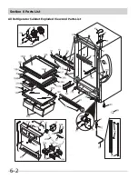
Page 68: ...Section 6 Parts List 6 2 All Refrigerator Cabinet Exploded View And Parts List ...
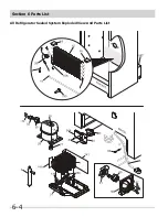
Page 70: ...Section 6 Parts List 6 4 All Refrigerator Sealed System Exploded View And Parts List ...
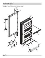
Page 72: ...Section 6 Parts List 6 6 All Freezer Door Exploded View And Parts List ...
Page 74: ...Section 6 Parts List 6 8 All Freezer Cabinet Exploded View And Parts List ...
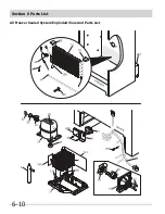
Page 76: ...Section 6 Parts List 6 10 All Freezer Sealed System Exploded View And Parts List ...
Page 78: ...Section 6 Parts List 6 12 Notes ...
Page 82: ...Section 7 Troubleshooting 7 4 Notes ...
Page 83: ...Section 8 Wiring Diagram 8 1 All Refrigerator Wiring Diagram ...
Page 84: ...8 2 Section 8 Wiring Diagram All Freezer Wiring Diagram ...


