32/38
-
5
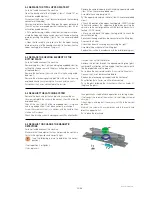
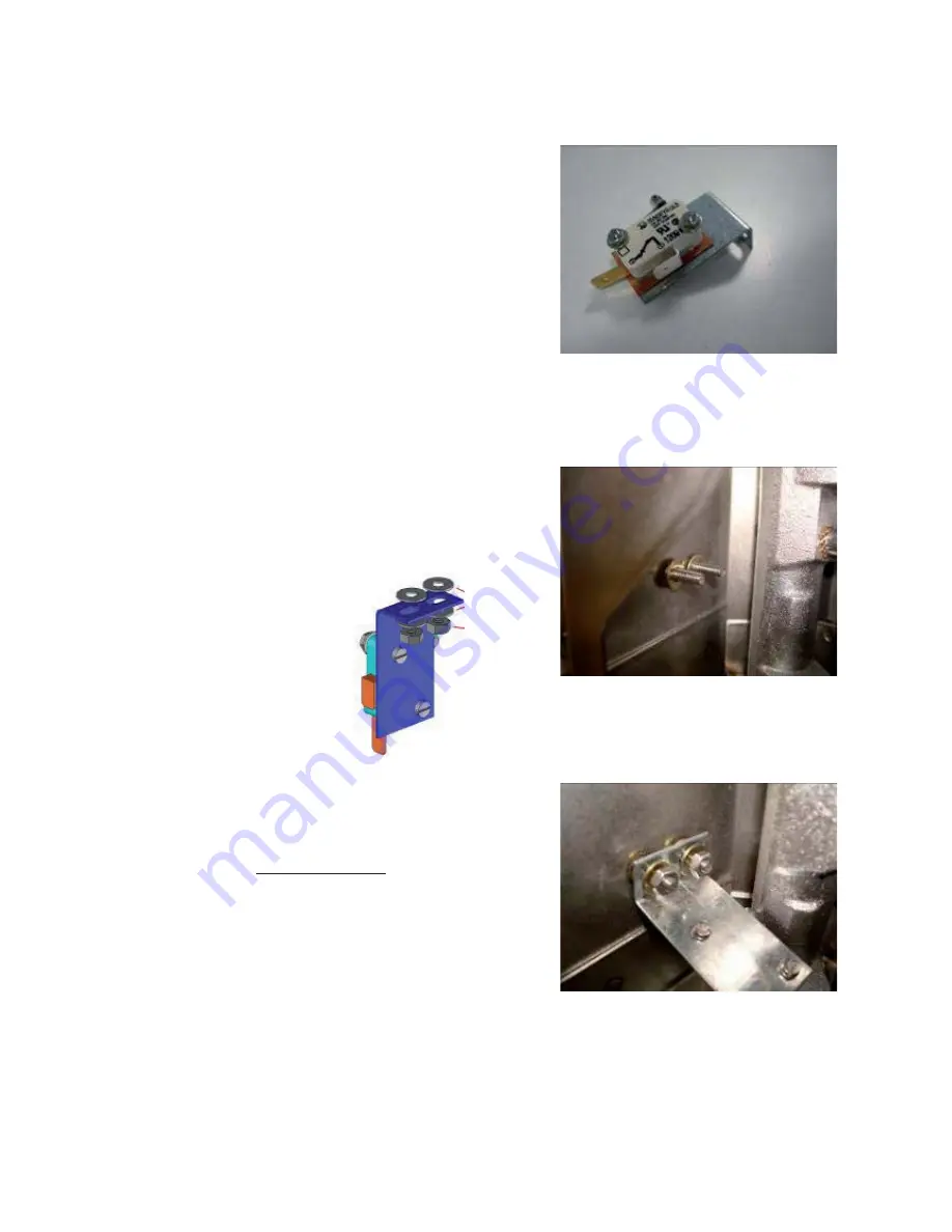
Remove the micro switch and mount
it on the new support .
This operation is mandatory
(Screwdriver for M3 and
Wrench 7mm or socket 7mm)
-
6
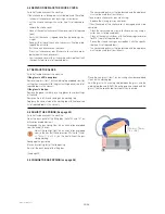
Mount 2 washers M4 on the welded
screws of the tilting box
-
7
Mount the micro switch support
The wheel must touch the aluminium axis
Mount 2 washers M4
Mount the 2 nuts
delivered in the kit
Tighten the nuts by hand
Summary of Contents for HSG Panini
Page 1: ...Service Manual GB 07 2009 HSG Panini Service manual ...
Page 2: ...2 2 50mm 50mm 7 5 190mm ...
Page 3: ......
Page 4: ......
Page 11: ...7 38 Explanation on software settings EU Version U207 ...
Page 12: ...8 38 Explanation on software settings US Version U202 U208 ...
Page 28: ...24 38 HSPP tech GB 03 09 ADJUST THE SPRINGS ...
Page 29: ...25 38 HSPP tech GB 03 09 ...
Page 30: ...26 38 ...
Page 31: ...27 38 5 9 CHANGE THE GAS SPRING ...
Page 32: ...28 38 ...
Page 33: ...29 38 ...
Page 41: ...37 38 ...
Page 43: ......
Page 49: ...Vue éclatée Couvercle Cover exploded view Explosionszeichnung Haube F HSPP FR 03 09 ...
Page 51: ...Esploso coperchio Despiece tapa Sprängskiss lock H HSPP FR 03 09 ...
Page 53: ...Vue éclatée Articulation Hinge exploded view Explosionszeichnung Gelenk J HSPP FR 06 09 ...
Page 55: ...Esploso articolazione Despiece articulación Sprängskiss Rotation L HSPP FR 06 09 ...
Page 59: ...Vue éclatée Electrique Electric exploded view Explosionszeichnung Elektrik P HSPP FR 03 09 ...
Page 61: ...Esploso elettronica Despiece electricidad Sprängskiss elektronik R HSPP FR 03 09 ...
Page 64: ......

