SOI/DT 2006-01 dmm
39/71
599 37 47-13
5.6 Pressure
switch
5.6.1 General
characteristics
The function of the pressure switch is to determine the quantity of water to
be introduced into the tub. In other words:
Ö
It controls the water fill levels during the washing phases.
Ö
It acts as an anti-boiling safety device when connected in series to the
heating element.
Ö
It can also act as an anti-overflow safety device if connected in series to
the drain pump.
Ö
It can act as an anti-foam device during the spin phases.
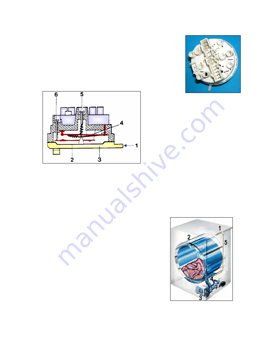
1. Air inlet aperture
2. Diaphragm
3. Internal
chamber
4. Contact strip (rapid cut-in)
5. Level regulation screw
6. Differential regulation screw
The internal chamber is connected via a small tube to the pressure chamber. When water is introduced into
the tub, the pressure in this chamber increases. When the pressure reaches a pre-determined level, the
membrane causes the contact strip to trip (rapid-action), which switches the contact from "empty" to "full".
Two regulation screws are fitted to the cover, one for the level, the other for the differential, i.e. the point at
which the strip returns to the "empty" position when the level of water in the tub decreases.
5.6.2 Pressure switch hydraulic circuit
1. Pressure
switches
2. Tub
3. Filter
body
4. Pressure chamber on the tube between the tub
and the filter body
5. Pressure switch tubes
Normally, all appliances are fitted with one or two
pressure switches (in rare cases, an appliance may
feature three pressure switches). Each pressure
switch controls from one to three levels of water in
the tub.
The small tube from the pressure switches may be
connected to the pressure chamber, which is located
beneath the tub.
One or two pressure switches may be connected to
the pressure chamber, depending on the model.


