Doc. No.:
560001 EG
Page:25
Ed.1" 08-2014
From ser. no.:
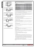
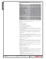
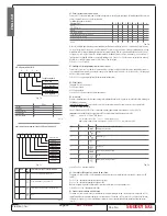
set point
allarme bassa temperatura
allarme alta temperatura
A0
A0
AL
Fig. 7.i
ENGLISH
Warnings for using the continuous cycle
The low temperature alarm is also used in the continuous cycle (see the description of parameter cc’.
In fact, if the temperature falls to the alarm level, the continuous cycle is stopped automatically, even if the selected time has not
yet elapsed. This deactivation, however, does not involve an alarm signal.
Default: AL =0 => low temperature alarm disabled.
Note:
for the control probe alarm, the low temperature alarm is reset and monitoring reinitialised.
AH: High temperature alarm
This is used to determine the activation threshold for the high temperature alarm.
Relative threshold for high temperature alarm = (set point) + (value of AH)
AH=0 => Alarm disabled;
Absolute threshold for high temperature alarm = value of AH.
AH=200 => Alarm disabled.
Important:
if the threshold AH is selected as relative, the value for disabling the alarm is 0, while if selected as absolute, the
alarm disabling value is 200
.
Warnings for the relative threshold:
• the value of AH does not indicate the alarm temperature, but the maximum permissible deviation from the set point; conse-
quently, changing the set point automatically changes the high temperature alarm, while the maximum deviation allowed
(=AH) remains fi xed.
Warnings:
• the high temperature alarm has automatic reset: this means that if the temperature returns above/below the minimum value
envisaged, the alarm signal is cancelled automatically
• in the event of a control probe alarm, the high temperature alarm is reset and monitoring reinitialised.
Default: AH=0 => high temperature alarm disabled.
Ad: Temperature alarm delay
Indicates after how many minutes the temperature alarm is signalled when the temperature threshold is exceeded.
Warnings:
• Setting a delay for signalling the temperature alarm may help eliminate false alarms due to interference on the probe signal or
brief situations (for example, the door to the cold room opened for a short period);
• no temperature alarms are generated during the defrost and continuous cycle procedures;
• the temperature alarm is delayed by the time d8 after the defrost and by the time c6 after the continuous cycle. At the end of these
two times, the temperature alarm, if detected, is signalled without waiting for the time set for Ad. If d8 and c6 are set to zero, the
temperature alarm is signalled after the time Ad;
• as already indicated by the default value for parameters AL and AH, the instruments are programmed in the factory with the relevant
thresholds, and the high and low temperature alarms are disabled. The alarms, when enabled, activate the buzzer, if enabled, and
show a code on the display: HI for the high temperature and LO for the low temperature alarm.
The following conditions generate the temperature alarms:
• high temperature alarm: the temperature measured by the virtual control probe is above the threshold set for parameter AH;
• low temperature alarm: the temperature measured by the virtual control probe is below the threshold set for parameter AL.
Default: Ad=120 => 120 minute delay for the temperature alarms.
A4: Multifunction digital input confi guration
In the ir33 series, this parameter and the model of controller used defi ne the meaning of the multifunction digital input.
The possibilities are described below:
A4=0 Input not active: the multifunction digital input is not used and is the factory-specifi ed confi guration for all versions.
A4=1 Immediate external alarm: the digital input can be connected to an external alarm that requires immediate activation (for
example, high pressure alarm or compressor thermal overload). Specifi cally, the alarm is detected when the contact opens (normal
operation with contact closed). The activation of the alarm:
• shows the message on the display (IA);
• activates the buzzer, if enabled;
• activates the alarm relay, if selected;
• involves the following actions on the actuators:
- compressor: operates depending on the values assigned to parameter A6 (stop compressor from external alarm).
- fans: continue to operate according to the fan parameters (F).
When stopping the compressor, the minimum ON time (c3) is ignored. When the alarm stops, the
defrost and continuous cycle can be performed again, and the compressor returns to normal operation.
Important warning:
remember that in order to ensure the safety of the unit in the event of serious alarms, all the electromechanical
safety devices required to guarantee correct operation must be fi tted on the unit.
Note:
• if more than one digital input is confi gured as the immediate alarm, the alarm will be generated when at least one of the inputs
is open.
• if control with two compressor steps is selected (with or without rotation, H1, H5 = 12 or 13) the immediate external alarm acts
on both steps.
A4=2 Delayed external alarm
The delayed external alarm is equivalent to the immediate external alarm (A4=1), except that this alarm is signalled after the
time A7 from when it is detected (‘dA’ signal). This confi guration is especially useful for managing the low pressure alarm. In fact,
when starting for the fi rst time, the unit often detects a low pressure alarm due to the environmental conditions rather than the
malfunctioning of the unit.
Setting a delay for the alarm will avoid false signals. In fact, by suitably calculating the delay, if the low pressure is due to environmental
conditions (low temperature), the alarm will be automatically reset before the delay has elapsed.
Note:
• if ‘A7’=0, the activation of the alarm does not cause the compressor to operate according to the values assigned to the parameter
‘A6’ (stop compressor from external alarm); on the other hand, the ‘dA’ signal is displayed, the icon fl ashes, the buzzer and the
alarm relay (if selected) are activated;


