background image

8

S

Keep blade below waist level. It will be eas-
ier to maintain control of unit.

S

Do not raise the engine above your waist as
the blade can come dangerously close to your
body.

S

Do not swing the unit with such force that
you are in danger of losing your balance.

Bring the powerhead engine to cutting speed
before entering the material to be cut.
If the blade does not turn when you squeeze the
throttle trigger of the powerhead, make sure the
attachment is fully inserted into the coupler.
Always release the throttle trigger and allow
powerhead engine to return to idle speed
when not cutting. The blade should not turn
while the engine is running at idle. If the blade
turns at idle, do not use your unit. Refer to the
CARBURETOR ADJUSTMENT section of
the powerhead manual or contact your autho-
rized service dealer.

S

Maintain good firm footing while using the
unit. Do this by planting feet firmly in a com-
fortable apart position.

S

Cut while swinging the upper part of your
body from left to right.

S

As you move forward to the next area to cut,
be sure to maintain your balance, and footing.

Cut using the 2
o’clock to 4 o’clock
position of the
blade

2 o’clock

4 o’clock

RECOMMENDED CUTTING POSITION

WARNING:

The operator or others

must not try to clear away cut material with the
engine running or the blade turning to avoid seri-
ous injury. Stop engine and blade before remov-
ing materials wrapped around blade or shaft.

MAINTENANCE

WARNING:

Always stop unit and dis-

connect spark plug wire before performing
maintenance.

CHECK FOR DAMAGED OR
WORN PARTS

Contact an authorized service dealer for re-
placement of damaged or worn parts.

S

Blade Shield -- Discontinue use of brushcut-
ter attachment if shield is damaged.

CHECK FOR LOOSE FASTENERS
AND PARTS

S

Blade nut

S

Fasteners

INSPECT AND CLEAN UNIT
AND DECALS

S

After each use, inspect complete unit for loose
or damaged parts. Clean the unit and decals
using a damp cloth with a mild detergent.

S

Wipe off unit with a clean dry cloth.

BLADE MAINTENANCE

WARNING:

The blade will continue to

spin after the engine stops or after the throttle
trigger has been released. To avoid serious
injury, make sure the blade has stopped
coasting and disconnect the spark plug before
performing work on the blade.

WARNING:

Always replace a blade

that is bent, warped, cracked, broken, or dam-
aged in any other way.

Never attempt to

straighten and reuse a damaged blade. Use
only specified replacement blade. Wear pro-
tective gloves when handling or performing
maintenance on the blade to help avoid injury.

S

Check blade for flatness periodically. Lay
the blade on a flat surface to inspect for flat-
ness. Throw away a blade that is not flat.

SERVICE AND ADJUSTMENTS

BLADE REPLACEMENT

WARNING:

The blade will continue to

spin after the engine stops or after the throttle
trigger has been released. To avoid serious
injury, make sure the blade has stopped
coasting and disconnect the spark plug before
performing work on the blade.

WARNING:

Wear protective gloves

when handling or performing maintenance on
the blade to avoid injury. The blade is sharp and
can cut you even when it is not moving.
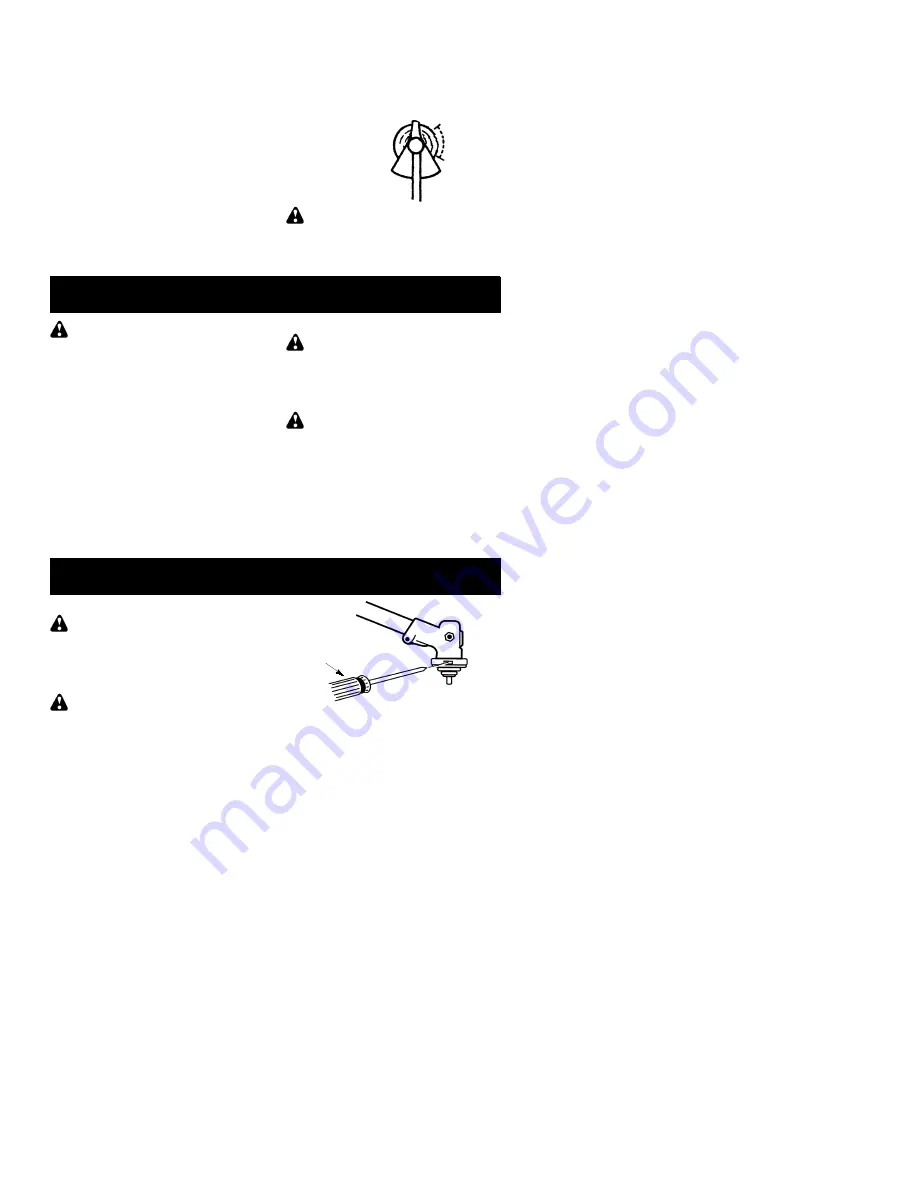
1.

To remove the blade, align hole in the dust
cup with the hole in the side of the gear-
box by rotating the blade.

2.

Insert a small screwdriver into aligned
holes. This will keep the shaft from turn-
ing while loosening the blade nut.

Screwdriver

3.

While holding the screwdriver in position,
remove blade nut by turning clockwise as
you are facing the nut.

4.

Remove both washers and the blade
from the blade shaft. Leave the dust cup
on the gearbox.

Summary of Contents for U4000C

Page 1: ...ctions et bien respecter tous les avertisse ments et toutes les instructions de sécurité Tout défaut de le faire pourrait entraîner des blessures graves Instruction Manual Manual de Instrucciones Manuel d Instructions U4000C Electrolux Home Products Inc 250 Bobby Jones Expressway Augusta GA 30907 Copyright E2003 Electrolux Home Products Inc 530164695 12 8 03 NOT DESIGNED FOR USE WITH ELECTRIC POWE...

Page 2: ...tire in structionmanualbeforeassembling andusing theunit Restrict the use of this unit to persons who read understand and follow the warn ings and instructions in this manual andon the unit Never allow children to operate this unit SAFETY INFORMATION ON THE UNIT INSTRUCTION MANUAL DANGER Never use flailing devices DANGER Blade can thrust violently away from material it does not cut Blade thrust ca...

Page 3: ... contactinganyobject Hold theunit byhand do not use the shoulder strap for support S Keep others away when making carburetor adjustments S Use only recommended Poulan Weed Eater accessories and replacement parts S Have all maintenance and service not ex plained in this manual performed by an au thorized service dealer FUEL SAFETY S Mix and pour fuel outdoors S Keep away from sparks or flames S Use...

Page 4: ...nts place the unit on a flat surface for stability 1 Loosen the coupler by turning the knob counterclockwise Coupler Knob LOOSEN TIGHTEN 2 Remove the shaft cap from the brushcut ter attachment if present 3 Position locking release button of attach ment into guide recess of coupler 4 Push the attachmentinto the coupleruntil the locking release button snaps into the primary hole 5 Beforeusing the un...

Page 5: ... offcompletely before use and placed over the screw holes on thelower shoulder strapclamp Thesetabs are not needed for powerheads with a 7 8 2 2 cm upper shaft Spacer Tabs LOWER SHOULDER STRAP CLAMP Spacer Tabs positioned for use on 1 2 5 cm diameter upper shaft 1 Place the upper shoulder strap clamp overtheuppershaftabove thehandlebar 2 Position the lower shoulder strap clamp under the upper shaf...

Page 6: ...nd brush up to 1 2 inch 1 cm in diameter BLADE SHIELD TheBLADE SHIELD provides protectionfrom the spinning blade WARNING Always disconnect pow erhead spark plug before removing or instal ling attachments REMOVING BRUSHCUTTER AT TACHMENT OR OTHER OPTIONAL ATTACHMENTS CAUTION When removing or installing at tachments place the powerhead and attach ment on a flat surface for stability 1 Loosen the cou...

Page 7: ...s reaction can cause serious injury such as amputation Carefully study this section It is important that you understand what causes blade thrust how you can reduce the chance of its occur ring and how you can remain in control of unit if blade thrust occurs S WHAT CAUSES BLADE THRUST Blade Thrust can occur when spinning blade con tacts anobjectthatitdoes notcut This contact causes blade to stop fo...

Page 8: ...ushcut ter attachment if shield is damaged CHECK FOR LOOSE FASTENERS AND PARTS S Blade nut S Fasteners INSPECT AND CLEAN UNIT AND DECALS S After each use inspect complete unit for loose or damaged parts Clean the unit and decals using a damp cloth with a mild detergent S Wipe off unit with a clean dry cloth BLADE MAINTENANCE WARNING The blade will continue to spin after the engine stops or after t...

Page 9: ...pears to be un even the blade is not centered and you must reinstall STORAGE WARNING Perform the following steps after each use S Allow attachment and gearbox to cool be fore storing or transporting S Store attachment with blade shield in place Position attachment so that any sharp ob ject cannot accidentally cause injury S Store theattachmentin adry well ventilated area out of the reach of childr...

Page 10: ... ups sparkplugs filters cuttingline orrotating head parts that will wear and require replace ment with reasonable use during the warranty period This warrantydoes not cover predeliv ery setup or normal adjustments explained in the instruction manual THIS WARRANTY GIVES YOU SPECIFIC LEGAL RIGHTS AND YOU MAY HAVE OTHER RIGHTS WHICH VARY FROM STATE TO STATE NO CLAIMS FOR CONSEQUENTIAL OR OTHER DAMAGE...

Reviews: