background image

WARM & SERVE DRAWER INSTALLATION INSTRUCTIONS

2

c

/

25 

5

/

16

"

(64.3 cm)

24" (64.3 cm) Max.

23 

5

/

8

" (60 cm) Min.

c

/

12 

21

/

32

"

(32.15 cm)

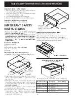
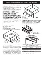
Figure 1

Important Notes to the Installer

1.

Read all instructions contained in these installation
instructions before installing appliance.

2.

Remove all packing material from appliance before
connecting the electrical supply.

3.

Observe all governing codes and ordinances.

4.

Be sure to leave these instructions with the consumer.

Important Note to the Consumer

Keep these instructions for future reference.

IMPORTANT SAFETY
INSTRUCTIONS

Be sure your appliance is installed and plugged

into a 120 Volt grounded outlet.

This appliance must be electrically grounded in

accordance with the National Electrical Code ANSI/
NFPA No. 70—latest edition in the United States,
or CSA C22.1, Part 1 in Canada, and local code
requirements.

Tools You Will Need

Phillips® Screwdriver
Pencil
Ruler or Tape Measure and Straight-edge
Hand Saw or Saber Saw
Spirit Level

Warm & Serve Drawer Installation

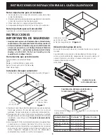
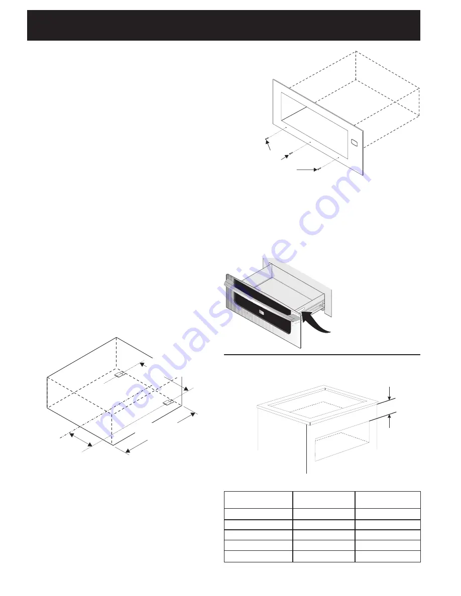
1.Locate the 2 anti-tip brackets supplied as shown on fig. 1.

Figure 2

Use screws
supplied to attach
drawer to front of
cabinet.

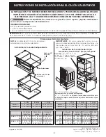
Combination Warm & Serve Drawer

and Cooktop Installation

A

Minimum Depth Spacing To Clear Cooktop Burner Box

2.Slide drawer into cutout opening until front frame of

drawer is flush against cabinet. Be careful not to pinch
electrical cord.

3.Remove the drawer as instructed in the Use & Care

Guide and secure drawer housing to cabinet using the
3 nickel-plated screws supplied (see Figure 2). 

Do not

overtighten screws.

4.The 60" (152 cm) appliance power cord can now be

connected into the 120 Volt outlet.

5.Proceed with mounting built-in oven above the drawer

(if applicable). Follow installation instructions provided
with built-in oven. Make sure to use anti-tip brackets
supplied with the built-in oven.

Model and Serial Number Location

The serial plate is located as shown below.

When ordering parts for or making inquiries about your
Warm & Serve Drawer, always be sure to include the
model and serial numbers and a lot number or letter from
the serial plate on your Warm & Serve Drawer.

Serial Plate Location

Electric Cooktop

E30IC75, E36IC75

E30EC65, E36EC65

E36EC75

E30EC70, E36EC70

Gas Cooktop

E36GC75

Spacing "A"

4.5" (11.43cm)

6.0" (15.24cm)

7.5" (19.05cm)

8.5" (21.59cm)

5.0" (12.7cm)

Summary of Contents for WARM & SERVE DRAWER

Page 1: ...mum distance to floor 41 2 11 4 cm IMPORTANT The Warm Serve Drawer runs off a single phase three wire 120 volt 60 hertz AC only electrical supply with ground H 11 7 8 30 2 cm Min is a Critical dimension and has to be respected Bottom of oven cutout Caution Two 3 7 6 cm wide X 3 4 1 9 cm thick planks have to be install and they should be able to support 200 pounds 90 7 Kg Printed in the USA J 3 7 6...

Page 2: ... shown on fig 1 Figure 2 Use screws supplied to attach drawer to front of cabinet Combination Warm Serve Drawer and Cooktop Installation A Minimum Depth Spacing To Clear Cooktop Burner Box 2 Slide drawer into cutout opening until front frame of drawer is flush against cabinet Be careful not to pinch electrical cord 3 Remove the drawer as instructed in the Use Care Guide and secure drawer housing t...

Page 3: ... Abertura del Cajón calentador Cajón Calentador Cable de 60 152 cm Distancia Minima del piso 4 1 2 11 4 cm P N 318201809 0709 Rev C English pages 1 2 Español páginas 3 4 Français pages 5 6 Notes Pages 7 8 B C A D G H F E J Precaución Dos tablas de 3 7 6 cm por 3 4 1 9 cm necesitan ser instaladas y deberán soportar 200 libras 90 7 Kg Parte inferior del horno H 11 7 8 30 2 cm Min es una dimensión cr...

Page 4: ...a dentro de la abertura de la abertura hasta que el marco frontal del cajón esté a ras contra el gabinete Tenga cuidado de no pinchar el cable eléctrico 3 Remover el cajón como indica el manual de uso y cuidado asegure el marco contra el gabinete utilizando los tornillos niquelados vea la Figura 2 No apriete demasiado los tornillos 4 Elcablede60 152cm delelectrodomésticopuedeahora conectarse en un...

Page 5: ...201809 0709 Rev C English pages 1 2 Español páginas 3 4 Français pages 5 6 Notes pages 7 8 B C A D G H F E J Attention Deux planches de 3 7 6 cm de large X 3 4 1 9 cm d épais doivent être installées et elles doivent être en mesure de supporter un poids de 200 lbs 90 7 Kg Imprimé aux Etats Unis Bas du découpage pour le four J 3 7 6 cm Max La boîte de jonction électrique pour le four encastré doit ê...

Page 6: ...tirez le tiroir tel qu expliqué dans le manuel d utilisation et d entretien et fixez le châssis du tiroir à l armoire à l aide des 3 vis plaquées au nickel fournies Ne serrez pas les vis outre mesure voir fig 2 4 Le cordon d alimentation de l appareil de 60 152 cm peut à présent être branché à la prise murale de 120 volts 5 Procédezmaintenantaumontagedufourencastrésuperposé au tiroir réchaud s il ...

Page 7: ...7 INSTRUCTIONS D INSTALLATION POUR LE TIROIR RÉCHAUD Notes Notas ...

Page 8: ...8 INSTRUCTIONS D INSTALLATION POUR LE TIROIR RÉCHAUD Notes Notas ...

Reviews: