


Installation manual
31
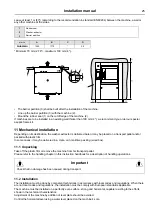
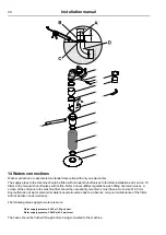
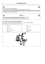
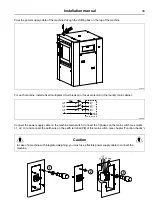
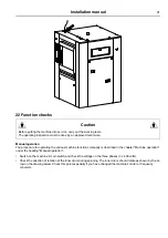
The hereunder example sketch shows the connection of the machine to the different inlets.
A
Hard water inlet DN 20 (¾" BSP) only this one for Clean Room Option
D
Manual stop valve DN 20 (¾" BSP) (provided by customer)
E
Water filter (provided)
F
Male nipple DN 20 (¾" BSP) (provided)
G
Flexible pipe DN 20 (¾" BSP) (provided)
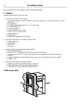
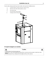
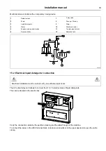
15 Liquid detergents connection
Caution
Liquid detergents are particularly aggressive.
We advise you to use only products with pH lower than 9 in order to avoid the machine's rubbers from being
attacked.
Dilute imperatively all of your detergents before letting them flow into the machine.
Summary of Contents for WHB5 500H
Page 2: ......
Page 4: ......
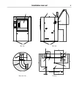
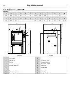
Page 21: ...Installation manual 21 Back view Right view Drain connection Top view ...
Page 42: ...42 Installation manual ...
Page 45: ......


