40
Installation manual
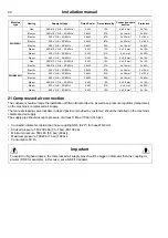
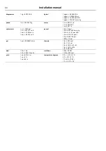
Machine
type
Heating
Supply Voltage
Rated Power
Rated Intensity
Connection cable
section
Protection
WH5500H
Gas
380/415 V 3+E ~ 50/60 Hz
5 kW
12 A
4 x 2.5 mm²
3 x 16 A
Electric
380/415 V 3+E ~ 50/60 Hz
38 kW
57 A
4 x 16 mm²
3 x 63 A
Electric
230 V 3+E ~ 50/60 Hz
38 kW
97 A
4 x 25 mm²
3 x 125 A
Electric
200 V 3+E ~ 50/60 Hz
38 kW
87 A
4 x 25 mm²
3 x 125 A
Electric
480 V 3+E ~ 50/60 Hz
38 kW
50 A
4 x 16 mm²
3 x 63 A
Steam
380/415 V 3+E ~ 50/60 Hz
5 kW
12 A
4 x 2.5 mm²
3 x 16 A
Steam
230 V 3+E ~ 50/60 Hz
5 kW
21 A
4 x 6 mm²
3 x 25 A
Steam
480 V 3+E ~ 50/60 Hz
5 kW
10 A
4 x 2.5 mm²
3 x 16 A
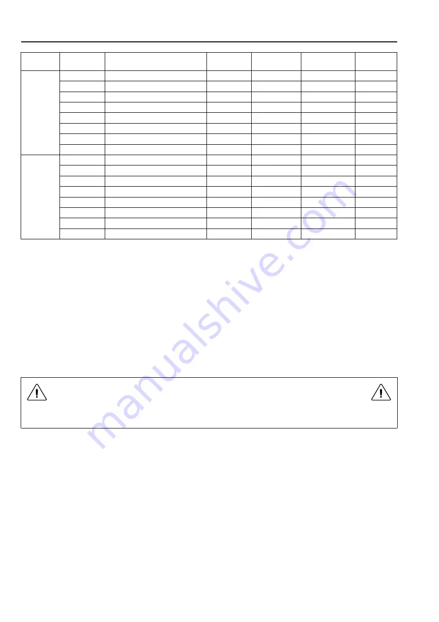
WHB5500H
Gas
380/415 V 3+E ~ 50/60 Hz
5 kW
12 A
4 x 2.5 mm²
3 x 16 A
Electric
380/415 V 3+E ~ 50/60 Hz
38 kW
57 A
4 x 16 mm²
3 x 63 A
Electric
230 V 3+E ~ 50/60 Hz
38 kW
97 A
4 x 25 mm²
3 x 125 A
Electric
200 V 3+E ~ 50/60 Hz
38 kW
87 A
4 x 25 mm²
3 x 125 A
Electric
480 V 3+E ~ 50/60 Hz
38 kW
50 A
4 x 16 mm²
3 x 63 A
Steam
380/415 V 3+E ~ 50/60 Hz
5 kW
12 A
4 x 2.5 mm²
3 x 16 A
Steam
230 V 3+E ~ 50/60 Hz
5 kW
21 A
4 x 6 mm²
3 x 25 A
Steam
480 V 3+E ~ 50/60 Hz
5 kW
10 A
4 x 2.5 mm²
3 x 16 A
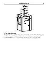
21 Compressed air connection
The customer should arrange the installation of filter/lubricator device, as well as a pressure regulator (manometer)
on the machine's compressed air supply.
The manual stopping valve lockable in closed position (provided by customer) should be installed on the machine's
compressed air supply.
The supply pipe should accept a pressure of at least 1 Mpa (10 bar) (145 psi).
• Connection diameter: rapid action hose coupling DN 6 (0.24") for hose Ø 6/8 mm.
• Advised pressure: 550-700 kPa (5,5-7 bar) (80-102 psi).
• Minimum pressure: 550 kPa (5,5 bar) (80 psi).
• Maximum pressure: 700 kPa (7 bar) (102 psi).
• Consumption 50 l/h.
Important
To avoid too big head losses, the compressed air supply pipe should be bigger in diameter than the coupling di-
ameter (DN 8 for example); in this case, put a 6/8-8/10 adapter.
Summary of Contents for WHB5 500H
Page 2: ......
Page 4: ......
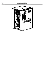
Page 21: ...Installation manual 21 Back view Right view Drain connection Top view ...
Page 42: ...42 Installation manual ...
Page 45: ......


