background image

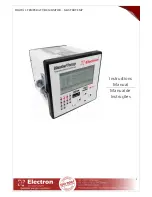
DIGITAL TEMPERATURE MONITOR – MASTERTEMP


Rev 

1.1 


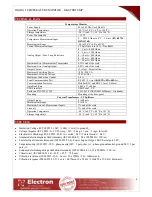
TECHNICAL DATA 


Temperature Monitor 

Power Supply 

48 to 265 Vdc/Vac 50/60 Hz 

Operation Temperature 

-20 °C to 70 °C (-4 ºF to 158 ºF) 

Storage temperature 

-50 °C to 60 °C (-58 ºF to 140 ºF) 

Power Consumption 

< 15 W 

Temperature Measurement Input 

2  –  PT100  Ohm  to  0°C    3  wires 

(EN  60751  - 

DIN 43760)


Measurement Range 

-50 to 250°C (-58 to 482ºF) 

Current Measurement Input 

CT Split Core 0 to 10 A  (True RMS) 

Analog Output / Max. Loop Resistence  

0 ... 1 mA - 8000 Ohms 
0 ... 5 mA - 1600 Ohms 
0 ... 10 mA - 800 Ohms 
0 ... 20 mA - 400 Ohms 
4 ... 20 mA - 400 Ohms 

Maximum Error Measurement Temperature 

0,25% end of the scale 

Maximum Error Analog Output 

0,25% end of the scale 

Output Contact 

13 relays – Potential free 

Maximum Switching Power 

70 W / 250 VA 

Maximum Switching Voltage 

250 Vac/Vdc 

Maximum Conduction Current 

6,0 A 

Serial Communication Port 

RS 485 – 2 wire 

(ANSI/TIA/EIA-485-A)


Communication Protocols 

Modbus RTU and DNP 3 Level 2 (Slave) 

Auto Baud Rate 

2,400 a 57,600 bps 

USB Front Port 

USB Serial – 2.0  

Enclosure DIN IEC 61554 

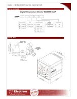
3,8x3,8x3,8 INCH (98x98x98mm) – Aluminum  

Mounting 

Mounting at the door panel 

Current Transformer - CT Split core 

Output Signal 

4 to 20 mA 

Measurement Range 

0 to10 A 

Maximum Error of Measurement Inputs 

1% end of the scale 

Linearity 

1% end of the scale 

Operation Temperature 

-40 °C to 85 °C (-40 ºF to 185 ºF) 

Storage temperature 

-50 °C to 60 °C (-58 ºF to 140 ºF) 


TYPE TEST 


 Insulation Voltage (IEC 60255-5): 2kV / 60Hz / 1 min. (to ground); 


Voltage impulse (IEC 60255-5): 1.2/50 

seg. / 5kV / 3 neg. e 3 pos. / 5 segs. Interval; 


Electrostatic Discharge (IEC 60255-22-2): Air mode = 8kV / Contact mode = 6 kV; 


Irradiated electromagnetic field immunity (IEC61000-4-3): 80 a 1000 MHz / 10V/m; 


Fast electrical transient immunity (IEC60255-22-4): Power./Input./Output=4KV/Serial port. 2kV; 


Surge immunity (IEC60255-22-5): phase/neutral 1kV, 5 per polar. (±) - phase-ground/neutral-ground 2kV, 5 per 
pole (±); 


Conduced electromagnetic perturbations immunity (IEC61000-4-6): 0,15 a 80 MHz / 10V/m; 


Climatic test (IEC60068-21-14): -40ºC + 85ºC / 72 hours; 


Vibration resistance (IEC60255-21-1): 3 axis / 10 a 150Hz / 2G / 160min/axis; 


Vibration response (IEC60255-21-1): 3 axis / 0,075mm-10 a 58 Hz / 1G de 58 a 150 Hz / 8min/axis; 


Summary of Contents for MASTERTEMP

Page 1: ...DIGITAL TEMPERATURE MONITOR MASTERTEMP 1 Instructions Manual Manual de Instruções ...

Page 2: ...ATION MASTERTEMP 20 DEFECTS SOLUTIONS 37 IMPORTANT RECOMMENDATIONS 37 WARRANTY STATEMENT 37 WARRANTY 38 REVIEW OF TECHNICAL MANUAL 38 Manual de Instruções Version 1 0 ÍNDICE PORTUGUÊS INTRODUÇÃO 39 PRINCIPAIS CARACTERÍSTICAS 40 DADOS TÉCNICOS 41 ENSAIOS DE TIPO ATENDIDOS 41 EXEMPLO DE APLICAÇÃO 42 CÓDIGO DE CATÁLOGO 43 DIMENSÕES 43 DIAGRAMAS DE LIGAÇÃO MASTERTEMP 44 CONHECENDO O MASTERTEMP 45 CONF...

Page 3: ...DIGITAL TEMPERATURE MONITOR MASTERTEMP ii RECOMENDAÇÕES IMPORTANTES 76 TERMO DE GARANTIA 76 TERMO DE GARANTIA 77 CONTROLE DE REVISÕES 77 ...

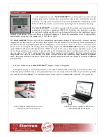
Page 4: ...0 to 5 mA 0 to 10 mA 0 to 20 mA or 4 to 20 mA For remote temperature readings of oil and winding temperatures MASTERTEMP provides 1 one digital output RS485 with protocol Modbus RTU and DNP 3 0 Level 2 to be selected by the user and allows access to all its monitoring parameters in real time It has pre settings for oil temperature alarm winding alarm oil trip winding trip operations of 1st and 2nd...

Page 5: ...o the load percentage of the transformer Consult on display and output serial to the transformer primary current kA Consult on display and output serial to the transformer secondary current A Consult on display and output serial to the maximum reached temperatures oil windings and environment Consult on display and output serial to the occurred failures in the equipment and sensors 01 contact rela...

Page 6: ...ront Port USB Serial 2 0 Enclosure DIN IEC 61554 3 8x3 8x3 8 INCH 98x98x98mm Aluminum Mounting Mounting at the door panel Current Transformer CT Split core Output Signal 4 to 20 mA Measurement Range 0 to10 A Maximum Error of Measurement Inputs 1 end of the scale Linearity 1 end of the scale Operation Temperature 40 C to 85 C 40 ºF to 185 ºF Storage temperature 50 C to 60 C 58 ºF to 140 ºF TYPE TES...

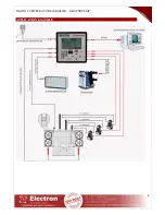
Page 7: ...DIGITAL TEMPERATURE MONITOR MASTERTEMP 4 APPLICATION EXAMPLE ...

Page 8: ...DIGITAL TEMPERATURE MONITOR MASTERTEMP 5 CATALOG CODE DIMENSION ...

Page 9: ...DIGITAL TEMPERATURE MONITOR MASTERTEMP 6 WIRING DIAGRAM MASTERTEMP ...

Page 10: ...nu naviagation Digits decrement Key for menu navigation Digits increment Key for menu naviagation return to previous screen and cancel operation without saving the last modifications USB input for parametrization download of configuration e firmware update Key for menu navigation Input for memory card micro SD CARD LCD Display with backlight Led for indication of ausence of micro SD CARD ...

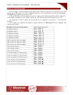
Page 11: ... parameter be available on display indication the MastertempTM must be configured with that parameter enabled Parameters to be show non the display Presentation form in display Temperature sensor 1 Sen1 0 0 C Temperature sensor 2 Sen2 0 0 C Temperature winding 1 Wnd1 0 0 C Temperature winding 2 Wnd2 0 0 C Temperature winding 3 Wnd3 0 0 C Final Temperature Gradient winding 1 FTG1 0 0 C Final Temper...

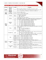
Page 12: ... SET change the variable with keys and press SET to confirm the changing If exiting the parameter or submenu without confirming the parameters return to previous values Submenu Parameters Variable Description Sensor Readout Type Readout BKP Ind Read mode menu for PT100 sensors BKP Makes the reading from both oil temperature points and indicates the average It enables the option to turn off the oil...

Page 13: ...configuration the last bit to be transmitted in the message to verify the data integrity ODD Last bit of the message is 1 EVEN Last bit of the message is 0 NONE No parity Protection Net ON OFF Configuration of the serial net protection OFF Protection system against parameters change OFF Parameters modification is allowed through the serial net ON Protection system against parameters change ON Para...

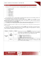
Page 14: ...50 to 250 C Cur 5 output range Min out 5 50 to 250 C Configures the temperature range to the current output 5 Winding 3 Min out 5 temperature value equivalente to the minimum level of analog scale 4 mA if selected scale is 4 20 mA Max out 5 temperature value equivalente to the maximum level of analog scale 20 mA if selected scale is 4 20 mA Max out 5 50 to 250 C SD Card Log Setup Time OFF 5 to 180...

Page 15: ...press SET to confirm 2nd Group Hour Meter Day Hours Minutes Edit Indicates how many days hours and minutes the 1st cooling group has worked To edit the days hours and minutes select the option EDIT and navigate with the keys to choose a variable Press SET to edit and using the keys change the value Next press SET to confirm Final Gradient Winding 1 Winding 2 Winding 3 50 to 250 C Indicates the rea...

Page 16: ...ssword is 0000 In case of lost or forgetting get in touch with Electron do Brasil and inform the Password Reminder Navigate by menus submenus and paratemeters with keys Select the submenu or parameter and press SET change the variable with keys and press SET to confirm the changing If exiting the parameter or submenu without confirming the parameters return to previous values Submenu Parameter Var...

Page 17: ... cooling actuation due load OFF Disables the colling actuation due load Winding 1 1 Group 50 to 200 Configuration of percentage load to start the cooling 2 Group 50 to 200 Winding 2 1 Group 50 to 200 2 Group 50 to 200 Winding 3 1 Group 50 to 200 2 Group 50 to 200 Due Temperature Oil 1 Group 50 to 250 C Configuration of temperature to start the cooling 2 Group 50 to 250 C Winding 1 1 Group 50 to 25...

Page 18: ...8 9 C Auxiliary Relay 2 Function Option OFF Temp Diff Sensor 1 Sensor 2 Winding 1 Winding 2 Winding 3 Indicates which variable will be mirrored on the auxiliary relay 2 Temp Diff reffers to the differential of temperature between Sensor 1 and Sensor 2 It s only a valid option in case both sensors are activated Temperature 50 to 250 C Actuation temperature for auxiliary relay 2 Delay ON OFF Delay t...

Page 19: ...arm RL 10 Winding 3 Trip RL 11 Failure Relay RL 12 Auxiliary Relay 1 RL 13 Auxiliary Relay 2 Test LED and LCD Attention when using this menu The relays will be actuated and the LEDs will be turned on so the operator can certify that everything is properly working However if the MasterTempTM is under operation connected to a transformer the test may cause a shutdown on the transformer Cooling Actua...

Page 20: ... touch with Electron do Brasil and inform the Password Reminder Navigate by menus submenus and paratemeters with keys Select the submenu or parameter and press SET change the variable with keys and press SET to confirm the changing If exiting the parameter or submenu without confirming the parameters return to previous values Submenu Parameter Variable Description Temperature Gradient OWG 1 OWG 2 ...

Page 21: ...BNT to the calculation this parameter will be adjusted to 0 zero Cooling Type 2M 1 0 to 2 0 Configuration of the cooling type used on the transformer 1 6 natural and forced oil 2 0 directed oil Nominal Current Winding 1 Winding 2 Winding 3 0 001 a 9 999 KA Configuration of the nominal current of the transformer in the windings Winding 1 nominal current at winding 1 Winding 2 nominal current at win...

Page 22: ... 1 3 Expoent 2M 1 6 ON e OF 2 0 OD Winding time constant 300 s Cooling Drive due Temperature 65 ºC 1º Group and 75 C 2º Group Oil temperature alarm 85 C ON 75 C OF Temperature alarm of the Windings 105 C Shutdown Temperature oil 110 C Shutdown Temp Winding 120 C Shutdown Delay 2 min Hysteresis for cooling shutdown 5 C ON Natural oil OF Forced oil OD Directed oil ...

Page 23: ... R 1000 10 10 10 50 0 250 0 Winding 3 Temperature Shutdown W R 1000 10 11 11 0 3 Register Cooling TypeRegistro W R 1 Cooling Actuation due Temperature 3 Cooling Actuation due Temperature and Load 12 12 50 0 250 0 Oil Temperature to 1st Cooling Group Actuation W R 1000 10 13 13 50 0 250 0 Winding 1 Temperature to 1st Cooling Group Actuation W R 1000 10 14 14 50 0 250 0 Winding 2 Temperature to 1st ...

Page 24: ... 29 0 300 Winding 3 Constant of Time to Thermal Inertia W R 1 1 30 30 0 200 HS Hot Spot Factor ABNT W R 1 10 31 31 10 15 HS Hot Spot Factor IEC W R 1 10 32 32 10 20 2M Winding Expoent W R 1 10 33 33 1 9999 Winding 1 Nominal Current W R 1 1000 34 34 1 9999 Winding 2 Nominal Current W R 1 1000 35 35 1 9999 Winding 3 Nominal Current W R 1 1000 36 36 1 9999 CT1 Current Transformation Ratio W R 1 1 37 ...

Page 25: ...egister Analog Type Output 0 Defines 0 to 1 mA W R 1 Defines 0 to 5 mA W R 2 Defines 0 to 10 mA W R 3 Defines 0 to 20 mA W R 4 Defines 4 to 20 mA W R 43 43 1 254 Serial Net Address R 1 1 44 44 0 0 0 defines forced cooling group as AUT GROUP1 W R 1 1 defines forced cooling group as ON GROUP1 W R 1 0 0 defines forced cooling group as AUT GROUP2 W R 1 1 defines forced cooling group as ON GROUP2 W R ...

Page 26: ... 1 Temperature R 1000 10 51 51 0 2000 Oil Sensor Temperature R 1000 10 52 52 0 2000 Winding 1 Temperature Sensor R 1000 10 53 53 0 2000 Winding 2 Temperature Sensor R 1000 10 54 54 0 2000 Winding 3 Temperature Sensor R 1000 10 55 55 0 2000 Sensor 1 Maximum Reached Temperature R 1000 10 56 56 0 2000 Oil Sensor Maximum Reached Temperature R 1000 10 57 57 0 2000 Winding 1 Maximum Reached temperature ...

Page 27: ... 1 enabled for Sensor 2 W R 3 Auxiliary Relay 1 enabled for Winding 1 W R 4 Auxiliary Relay 1 enabled for Winding 2 W R 5 Auxiliary Relay 1 enabled for Winding 3 W R 73 73 50 0 2500 Auxiliary Relay 1 temperature actuation W R 1000 10 74 74 0 100 Auxiliary Relay 1 histeresys W R 1 10 75 75 0 1 Register Delay Auxiliary Relay 1 Actuation 0 0 Delay OFF W R 1 Delay ON W R 76 76 0 6 Register Auxiliary R...

Page 28: ... 1 Winding 3 Alarm Return Manual W R 7 0 Winding 3 Shutdown Return Automatic W R 1 Winding 3 Shutdown Return Manual W R 8 0 Failure Relay Return Automatic W R 1 Failure Relay Return Manual W R 81 81 50 0 250 0 Sensor 1 Analog Output Minimum Temperature W R 1000 10 82 82 50 0 250 0 Sensor 1 Analog Output Maximum Temperature W R 1000 10 83 83 50 0 250 0 Sensor 2 Analog Output Minimum Temperature W R...

Page 29: ... 100 100 1 12 Month W R 1 1 101 101 2015 2099 Year W R 1 1 103 103 0 180 SD Card Data Log Interval W R 1 1 104 104 Register Cooling Exercise 0 0 Cooling Exercise OFF W R 1 Cooling Exercise ON W R 105 105 Register Type of Cooling Exercise 0 0 Weekly W R 1 Daily W R 106 106 0 6 Register Day of the Week for Cooling Exercise 0 Sunday W R 1 Monday W R 2 Tuesday W R 3 Wednesday W R 4 Thursday W R 5 Frid...

Page 30: ...st Cooling Group Actuation W R 1 10 124 124 0 2000 Winding 1 Load Percentage for 2nd Cooling Group Actuation W R 1 10 125 125 0 2000 Winding 2 Load Percentage for 2nd Cooling Group Actuation W R 1 10 126 126 0 2000 Winding 3 Load Percentage for 2nd Cooling Group Actuation W R 1 10 127 127 0 2000 Winding 1 Load Percentage for Shutdown W R 1 10 128 128 0 2000 Winding 2 Load Percentage for Shutdown W...

Page 31: ... R 20 4 0 Winding 3 2nd Cooling Group OFF R 1 Winding 3 2nd Cooling Group ON R 21 5 0 Manual 2nd Cooling Group OFF R 1 Manual 2nd Cooling Group ON R 22 6 0 Exercise 2nd Cooling Group ON R 1 Exercise 2nd Cooling Group OFF R 198 Register Sensors Failure Status 32 0 1 Sensor 1 Failure R 33 1 1 Oil Sensor Failure R 34 2 1 Winding 1 Sensor Failure R 35 3 1 Winding 2 Sensor Failure R 36 4 1 Winding 3 Se...

Page 32: ...F R 1 Countdown due Winding 3 ON R 69 5 0 Countdown due Auxiliary Relay 1 OFF R 1 Countdown due Auxiliary Relay 1 ON R 70 6 0 Countdown due Auxiliary Relay 2 OFF R 1 Countdown due Auxiliary Relay 2 ON R 201 Register Shutdown Stuats 81 1 0 Shutdwon due Oil OFF R 1 Shutdown due Oil ON R 82 2 0 Shutdown due Winding 1 OFF R 1 Shutdown due Winding 1 ON R 83 3 0 Shutdown due Winding 2 OFF R 1 Shutdown d...

Page 33: ...d or qualifiers supported in addition to the Highest DNP Levels Supported the complete list is described in the attached table Maximum Data Link Frame Size octet s Transmitted 292 Received must be 292 Maximum Application Fragment Size octet s Transmitted 1024 if 2048 must be configurable Received 249 must be 249 Maximum Data Link Re tries None Fixed at _______________________ Configurable range __...

Page 34: ...ble DIRETC OPERATE Never Always Sometimes Configurable DIRETC OPERATE NO ACK Never Always Sometimes Configurable Count 1 Never Always Sometimes Configurable Pulse On Never Always Sometimes Configurable Pulse Off Never Always Sometimes Configurable Lacth On Never Always Sometimes Configurable Lacth Off Never Always Sometimes Configurable Queue Never Always Sometimes Configurable Clear Queue Never A...

Page 35: ...nses Never When Device Restarts When Status Flags Change No other options are permitted Default Counter Object Variation No Counters Reported Configurable attach explanation Default Object ______________ Default Variation ______________ Point by point list attached Counters Roll Over at No Counters Reported Configurable attach explanation 16 Bits 32 Bits Other Value _____________ Point by point li...

Page 36: ...6 10 1 Binary Output 10 2 Binary Output Status 129 00 01 12 0 Control Block All Variations 12 1 Control Relay Output Block 3 4 5 6 17 28 129 echo of request 12 2 Pattern Control Block 12 3 Pattern Mask 20 0 Binary Counter All Variations 20 1 32 Bit Binary Counter 20 2 16 Bit Binary Counter 20 3 32 Bit Delta Counter 20 4 16 Bit Binary Counter 20 5 32 Bit Binary Counter without Flag 20 6 16 Bit Bina...

Page 37: ...ith Time 22 6 16 Bit Counter Change Event with Time 22 7 32 Bit Delta Counter Change Event with Time 22 8 16 Bit Delta Counter Change Event with Time 23 0 Frozen Counter Event All Variations 23 1 32 Bit Frozen Counter Event without Time 23 2 16 Bit Frozen Counter Event without Time 23 3 32 Bit Frozen Delta Counter Event without Time 23 4 16 Bit Frozen Delta Counter Event without Time 23 5 32 Bit F...

Page 38: ...ations 33 1 32 Bit Frozen Analog Event without Time 33 2 16 Bit Frozen Analog Event without Time 33 3 32 Bit Frozen Analog Event with Time 33 4 16 Bit Frozen Analog Event with Time 40 0 Analog Output Status All Variations 1 06 40 1 32 Bit Analog Output Status 40 2 16 Bit Analog Output Status 129 00 01 41 0 Analog Output Block All Variations 41 1 32 Bit Analog Output Block 41 2 16 Bit Analog Output...

Page 39: ...Internal Indications 2 00 index 7 81 1 Storage ObjeTC 82 1 Device Profile 83 1 Private Registration ObjeTC 83 2 Private Registration ObjeTC Descriptor 90 1 Application Identifier 100 1 Short Floating Point 100 2 Long Floating Point 100 3 Extended Floating Point 101 1 Small Packed Binary Coded Decimal 101 2 Medium Packed Binary Coded Decimal 101 3 Large Packed Binary Coded Decimal 110 String No Obj...

Page 40: ...r proper operation of the communication network 4 Only use with MasterTemp original accessories accompanying equipment TC Split core as they have been rigorously tested together to ensure maximum performance and efficiency in the functioning of the whole 5 Do not use the monitor directly in the SUN whenever it is installed on the pitch is important to have a panel with smoked glassso that ultravio...

Page 41: ...the degradation of components and parts of the product WARRANTY HOW TO USE THE WARRANTY To use the warranty the customer must send the product to Electron along with copy of the purchase invoice properly packaged to prevent any damage in transit To prompt attention is recommended to inform all possible details concerning the detected defect The same will be analyzed and subjected to full operation...

Page 42: ...enrolamentos saída digital RS485 com protocolos Modbus RTU e DNP 3 L2 escolhido pelo usuário que permite o acesso a todos os parâmetros do MASTERTEMP inclusive comando remoto de acionamentos em tempo real possui setpoints para parametrização de temperaturas para Alarme do Óleo Alarme de Enrolamento Desligamento Óleo Desligamento Enrolamentos Acionamento do 1 e 2 grupo de ventilação as sinalizações...

Page 43: ...ta no display da corrente do primário kA Consulta no display de temperaturas máximas atingidas óleo enrolamentos e ambiente Consulta no display de falhas ocorridas no equipamento 1 Contato para Alarme do Óleo NA NF sob pedido 3 Contatos para Alarme do Enrolamento NA NF sob pedido 1 Contato para Desligamento do Óleo NA NF sob pedido com temporização programável 3 Contatos para Desligamento do Enrol...

Page 44: ...al USB USB Serial Caixa 98 x 98 x 98 mm Alumínio Fixação Montagem Embutida em Painel Transformador de Corrente TC Split core Sinal de Saída 4 a 20mA Faixa de Medição 0 a 10 A Erro Máximo das Entradas de Medição 1 do fim da escala Linearidade 1 do fim da escala Temperatura de Operação 40 a 85 C ENSAIOS DE TIPO ATENDIDOS Tensão Aplicada IEC 60255 5 2kV 60Hz 1 min contra terra Impulso de Tensão IEC 6...

Page 45: ...MONITOR DIGITAL TEMPERATURE MASTERTEMP 42 EXEMPLO DE APLICAÇÃO ...

Page 46: ...MONITOR DIGITAL TEMPERATURE MASTERTEMP 43 CÓDIGO DE CATÁLOGO DIMENSÕES ...

Page 47: ...MONITOR DIGITAL TEMPERATURE MASTERTEMP 44 DIAGRAMAS DE LIGAÇÃO MASTERTEMP ...

Page 48: ...itos Tecla para navegar no menu retorno para tela anterior e cancelar operação sem salvar parâmetro alterado Entrada USB para parametrização download da parametrização e atualização de firmware Tecla para navegar no menu Entrada de cartão de memória micro SD CARD Display LCD com backlight Led piscando intermitente indicação de gravação no cartão de memória micro SD Led piscando continuamente falha...

Page 49: ...e podem ser indicadas no display Forma de apresentação no Display Temperatura do sensor 1 Sen1 0 0 C Temperatura do sensor 2 Sen2 0 0 C Temperatura do enrolamento 1 Enr1 0 0 C Temperatura do enrolamento 2 Enr2 0 0 C Temperatura do enrolamento 3 Enr3 0 0 C Gradiente final de temperatura do enrolamento 1 GFN1 0 0 C Gradiente final de temperatura do enrolamento 2 GFN2 0 0 C Gradiente final de tempera...

Page 50: ...ável automaticamente retorna o seu valor anterior Submenu Parâmetro Variável Descrição Confi leitura sensor T Leitura BKP Menu de configuração do modo de leitura dos sensores Pt100 BKP Faz a leitura dos dois pontos de temperatura do óleo e indica a média Habilita a opção de desligar o sensor de Óleo SEN2 Se ocorrer falha em um dos sensores PT100 continuará o cálculo de imagem térmica pelo sensor a...

Page 51: ...de dos dados NONE Sem paridade IMPAR Ultimo bit da mensagem a ser transmitido será 1 PAR Ultimo bit da mensagem a ser transmitido será 0 Proteção ON OFF Configuração da proteção da rede serial OFF Sistema de proteção contra alteração de parâmetros desligado permite fazer alterações de parâmetros pela rede seria ON Sistema de proteção contra alteração de parâmetros ligado não permite fazer alteraçõ...

Page 52: ...5 Min out 5 50 a 250 Configuração do range de temperatura máxima e Mínima para a saída de corrente 5 enrolamento 3 Min out 5 valor de temperatura equivalente a 4 mA para uma escala de 4 20 mA Max out 5 valor de temperatura equivalente a 20 mA para uma escala de 4 20 mA Max out 5 50 a 250 Log SD Card Tempo OFF 5 M A 180M Configuração do tempo de Log de integridade do equipamento no cartão micro SD ...

Page 53: ...ara confimar Horimetro 2 grupo Dia Horas Minutos Editar Indica a quantos dias horas e minutos o ventilador do grupo 2 fico ligado Para editar os dias as horas e os minutos selecionado a opção edite e navegue com as teclas e selecione a variável que deseja altere com as teclas altere o valor e pressione SET para confimar Gradiente final Enrolamento 1 Enrolamento 2 Enrolamento 3 50 a 250 Indica a te...

Page 54: ...terTemp não irá pedir a senha novamente De fabrica a senha do MasterTemp é 0000 Em caso de perda ou esquecimento da senha entre em contato com Electron do Brasil e informa o lembrete de senha Navegue pelos menus submenus e parâmetros com as teclas selecione o submenu ou o parâmetro desejado e pressione a tecla SET altere a variável com as teclas e pressione a tecla SET para confirmar a alteração c...

Page 55: ...ão por carregamento ON Habilita o acionamento da refrigeração por carregamento OFF Desabilita o acionamento da refrigeração por carregamento Enrolamento 1 1 Grupo 50 a 200 Configuração do percentual para o acionamento da ventilação para cada enrolamento 2 Grupo 50 a 200 Enrolamento 2 1 Grupo 50 a 200 2 Grupo 50 a 200 Enrolamento 3 1 Grupo 50 a 200 2 Grupo 50 a 200 Por temperatura Óleo 1 Grupo 50 a...

Page 56: ...s minutos Hora para início do exercício de Ventilação H final Horas minutos Hora para o término do exercício de Ventilação Rele auxiliar 1 Função OFF Sensor 1 Sensor 2 Enrol 1 Enrol 2 Enrol 3 OFF Rele auxiliar sem função Sensor 1 Rele auxiliar opera com a temperatura do sensor 1 Sensor 2 Rele auxiliar opera com a temperatura do sensor 2 Enrol 1 Rele auxiliar opera com a temperatura do enrolamento ...

Page 57: ...lamento 1 Enrol 2 Rele auxiliar opera com a temperatura do enrolamento 2 Enrol 3 Rele auxiliar opera com a temperatura do enrolamento 3 Temp 50 a 250 C Temp Selecionar a Temperatura para acionamento do Relé auxiliar1 Retar ON OFF Retar Tempo de Retardo para acionamento do relé auxiliar 2 OFF Tempo para acionamento desabilitado ON Tempo para acionamento habilitado O tempo do retardo para o desligam...

Page 58: ... 1 1 gropo derefrigeração após precionar a tecla SET RL 02 2 Grupo Refr Aciona o relé 2 2 gropo de refrigeração após precionar a tecla SET RL 03 Alarme do óleo Aciona o relé 3 alarme do óleo após precionar a tecla SET RL 04 Desl Óleo Aciona o relé 4 desligamento de óleo após precionar a tecla SET RL 05 Alarme Enrol 1 Aciona o relé 5 alarme do enrolamento 1 após precionar a tecla SET RL 06 Desl Enr...

Page 59: ...asterTemp não irá pedir a senha novamente De fabrica a senha do MasterTemp é 0000 Em caso de perda ou esquecimento da senha entre em contato com Electron do Brasil e informa o lembrete de senha Navegue pelos menus submenus e parâmetros com as teclas selecione o submenu ou o parâmetro desejado e pressione a tecla SET altere a variável com as teclas e pressione a tecla SET para confirmar a alteração...

Page 60: ...everá estar obrigatoriamente ajustado em 1 0 Tipo de resfriamento 2M 1 0 a 2 0 Configuração do tipo de resfriamento utilizado no transformador 1 6 óleo natural e óleo forçado 2 0 óleo dirigido Corrente Nominal Enrol 1 Enrol 2 Enrol 3 0 001 a 9 999 KA Configuração da corrente nominal do transformador nos enrolamentos Enrol 1 corrente nominal do transformador no enrolamento 1 Enrol 2 corrente nomina...

Page 61: ...ento CTE 300 segs Temperatura de Acionamento do Ventilador TAR 65ºC 1º Grupo e 75 C 2º Grupo Alarme de Temperatura do óleo ATA SEN2 85 C ON 75 C OF Alarme de Temp dos Enrolamentos ATA SEN3 105 C Desligamento por Temp do óleo DTA SEN2 110 C Desligamento por Temp dos Enrolamentos DTA SEN3 120 C Tempo de Retardo de Desligamento TRD 2 min Histerese de Desligamento Resfriador HDR 5 C ON óleo Natural OF...

Page 62: ...mperatura de desligamento do Enrolamento 3 E L 1000 10 11 11 0 3 Registro Tipo de acionamento da ventilação E L 1 Acionamento da ventilação por Temperatura 3 Acionamento da ventilação por temperatura e por Carregamento 12 12 50 0 250 0 Temperatura de Acionamento do 1º grupo de ventilação do Sensor do Óleo E L 1000 10 13 13 50 0 250 0 Temperatura de Acionamento do 1º grupo de ventilação do Sensor d...

Page 63: ...cia térmica do Enrolamento 3 E L 1 1 30 30 0 200 HS Fator Hot Spot E L 1 10 31 31 10 15 HS Fator Hot Spot E L 1 10 32 32 10 20 2M Expoente de Enrolamento E L 1 10 33 33 1 9999 Corrente Nominal do Enrolamento1 E L 1 1000 34 34 1 9999 Corrente Nominal do Enrolamento2 E L 1 1000 35 35 1 9999 Corrente Nominal do Enrolamento3 E L 1 1000 36 36 1 9999 Relação de transformação de corrente do TC1 E L 1 1 3...

Page 64: ...L 1 Quando 1 define Saída Analógica de 0 a 5mA E L 2 Quando 2 define Saída Analógica de 0 a 10mA E L 3 Quando 3 define Saída Analógica de 0 a 20mA E L 4 Quando 4 define Saída Analógica de 4 a 20mA E L 43 43 1 254 Endereço de rede Serial L 1 1 44 44 0 0 Quando 0 define Ventilação forçada como AUT GRUPO1 E L 1 Quando 1 define Ventilação forçada como ON GRUPO1 E L 1 0 Quando 0 define Ventilação força...

Page 65: ...ado E L 50 50 0 2000 Temperatura no sensor1 L 1000 10 51 51 0 2000 Temperatura no sensor do Óleo L 1000 10 52 52 0 2000 Temperatura no sensor do Enrolamento1 L 1000 10 53 53 0 2000 Temperatura no sensor do Enrolamento2 L 1000 10 54 54 0 2000 Temperatura no sensor do Enrolamento3 L 1000 10 55 55 0 2000 Temperatura máxima atingida pelo sensor1 L 1000 10 56 56 0 2000 Temperatura máxima atingida pelo ...

Page 66: ... o Enrolamento 1 L 4 Habilita relé auxiliar 1 para o Enrolamento 2 L 5 Habilita relé auxiliar 1 para o Enrolamento 3 L 73 73 50 0 2500 Temperatura de acionamento relé auxiliar 1 E L 1000 10 74 74 0 100 Histerese do relé auxiliar 1 E L 1 10 75 75 0 1 Registro Tempo de Retardo para acionamento do relé auxiliar 1 E L 0 0 Tempo de Retardo desabilitado E L 1 Tempo de Retardo habilitado E L 76 76 0 6 Re...

Page 67: ...nrolamento 3 automático E L 7 0 Retorno do desligamento do enrolamento 3 automático E L 1 Retorno do desligamento do enrolamento 3 manual E L 8 0 Retorno do relé de falha automático E L 1 Retorno do relé de falha manual E L 81 81 50 0 250 0 Temperatura mínima da saída de corrente do Sensor 1 E L 1000 10 82 82 50 0 250 0 Temperatura máxima da saída de corrente do Sensor 1 E L 1000 10 83 83 50 0 250...

Page 68: ...gistro de Exercício de ventilação 0 0 Exercício de Ventilação desabilitado E L 1 Exercício de Ventilação Habilitado 105 105 Registro de Tipo de exercício de Ventilação 0 0 Exercício de Ventilação Semanal E L 1 Exercício de Ventilação Diário 106 106 0 6 Registro de Dia da semana do Exercício de Ventilação 0 Exercício no Domingo E L 1 Exercício na Segunda feira E L 2 Exercício na Terça feira E L 3 E...

Page 69: ...2000 Percentual de Acionamento do 2º grupo de ventilação do Sensor do Enr 1 E L 1 10 125 125 0 2000 Percentual de Acionamento do 2º grupo de ventilação do Sensor do Enr 2 E L 1 10 126 126 0 2000 Percentual de Acionamento do 2º grupo de ventilação do Sensor do Enr 3 E L 1 10 127 127 0 2000 Acionamento do desligamento por percentual de carregamento enrolamento 1 E L 1 10 128 128 0 2000 Acionamento d...

Page 70: ...nto3 Acionado L 21 5 0 Ventilador Bomba manual desacionado L 1 Ventilador Bomba manual acionada L 22 6 0 Ventilador Bomba exercício desacionado L 1 Ventilador Bomba exercício acionada L 198 Registro Situação de Falha dos Sensores L 32 0 1 Falha do sistema do Sensor1 L 33 1 1 Falha do sistema do Sensor do Óleo L 34 2 1 Falha do sistema do Sensor do Enrolamento1 L 35 3 1 Falha do sistema do Sensor d...

Page 71: ...gamento do Enrolamento3 Desacionado L 1 Contagem de Desligamento do Enrolamento3Acionado L 69 5 0 Contagem de Relé Auxiliar 1 desacionado L 1 Contagem de Relé Auxiliar 1 Acionado L 70 6 0 Contagem de Relé Auxiliar 2 desacionado L 1 Contagem de Relé Auxiliar 2 Acionado L 201 Registro Situação do Desligamento 81 1 0 Desligamento do Óleo Desacionado L 1 Desligamento do Óleo Acionado L 82 2 0 Desligam...

Page 72: ...or qualifiers supported in addition to the Highest DNP Levels Supported the complete list is described in the attached table Maximum Data Link Frame Size octets Transmitted 292 Received must be 292 Maximum Application Fragment Size octets Transmitted 1024 if 2048 must be configurable Received 249 must be 249 Maximum Data Link Re tries None Fixed at _______________________ Configurable range __1 to...

Page 73: ...rable DIRECT OPERATE Never Always Sometimes Configurable DIRECT OPERATE NO ACK Never Always Sometimes Configurable Count 1 Never Always Sometimes Configurable Pulse On Never Always Sometimes Configurable Pulse Off Never Always Sometimes Configurable Latch On Never Always Sometimes Configurable Latch Off Never Always Sometimes Configurable Queue Never Always Sometimes Configurable Clear Queue Never...

Page 74: ...ponses Never When Device Restarts When Status Flags Change No other options are permitted Default Counter Object Variation No Counters Reported Configurable attach explanation Default Object ______________ Default Variation ______________ Point by point list attached Counters Roll Over at No Counters Reported Configurable attach explanation 16 Bits 32 Bits Other Value _____________ Point by point ...

Page 75: ... 06 10 1 Binary Output 10 2 Binary Output Status 129 00 01 12 0 Control Block All Variations 12 1 Control Relay Output Block 3 4 5 6 17 28 129 echo of request 12 2 Pattern Control Block 12 3 Pattern Mask 20 0 Binary Counter All Variations 20 1 32 Bit Binary Counter 20 2 16 Bit Binary Counter 20 3 32 Bit Delta Counter 20 4 16 Bit Binary Counter 20 5 32 Bit Binary Counter without Flag 20 6 16 Bit Bi...

Page 76: ... with Time 22 6 16 Bit Counter Change Event with Time 22 7 32 Bit Delta Counter Change Event with Time 22 8 16 Bit Delta Counter Change Event with Time 23 0 Frozen Counter Event All Variations 23 1 32 Bit Frozen Counter Event without Time 23 2 16 Bit Frozen Counter Event without Time 23 3 32 Bit Frozen Delta Counter Event without Time 23 4 16 Bit Frozen Delta Counter Event without Time 23 5 32 Bit...

Page 77: ...riations 33 1 32 Bit Frozen Analog Event without Time 33 2 16 Bit Frozen Analog Event without Time 33 3 32 Bit Frozen Analog Event with Time 33 4 16 Bit Frozen Analog Event with Time 40 0 Analog Output Status All Variations 1 06 40 1 32 Bit Analog Output Status 40 2 16 Bit Analog Output Status 129 00 01 41 0 Analog Output Block All Variations 41 1 32 Bit Analog Output Block 41 2 16 Bit Analog Outp...

Page 78: ... Internal Indications 2 00 index 7 81 1 Storage Object 82 1 Device Profile 83 1 Private Registration Object 83 2 Private Registration Object Descriptor 90 1 Application Identifier 100 1 Short Floating Point 100 2 Long Floating Point 100 3 Extended Floating Point 101 1 Small Packed Binary Coded Decimal 101 2 Medium Packed Binary Coded Decimal 101 3 Large Packed Binary Coded Decimal 110 String No Ob...

Page 79: ...0 Não utilizar o Monitor diretamente no SOL sempre que for instado em campo é importante que tenha um painel com vidro fumê afim que sejam filtrados os raios ultravioletas que agridem o policarbonato frontal desta maneira será prolongada a vida do equipamento TERMO DE GARANTIA O Mastertemp Electron tem prazo de garantia de dois anos contados a partir da data de venda consignada na nota fiscal com ...

Page 80: ...análise do produto e sua eventual manutenção somente será realizada pela equipe técnica da Electron do Brasil em sua sede Disponível para Downloads na Pagina de Internet http www electron com br downloads artigos tecnicos CONTROLE DE REVISÕES Revisão Nº 0 Junho 2015 Emissão Revisão Nº 1 0 Outubro 2015 Acrescentado Escala de Temperatura Graus Celsius e Graus Fahrenheit Revisão Nº 1 1 Outubro 2015 R...

Reviews: