The ED722 and ED726 loop driver can provide 300mA of continuous loop current, driving up to
126 devices using Apollo S90, XP95 or Discovery protocol.
Each loop is fully isolated electrically from the input power supply, giving continued operation
in the event of earth faults on the dc input, greatly increasing immunity to electrical noise and
eliminating false alarms due to crosstalk.
The ED722 and ED726 are similar but the ED726 can also accept up to 10 EDL addressable
gas detection interface modules. Both models are available with front panels, as used in the
ED700A 8 Loop Control Panel, or without front panels for use in the ED816A. For the full
failsafe features to be available on the ED816A the ED722 / ED726 front panel lamps and
switches are relocated on the ED816A I/O motherboard.
FAIL SAFE OPERATION
Each module within the system (ED722/6 loop modules, ED816A Display module and ED816
I/O module) communicate with each other using an industry standard I2C bus. In the event of
a communications failure, or a fault developing on any of the modules, creating a
communications failure, the loop cards continue to operate autonomously.
The loop modules are directly connected to the following normally energised relays mounted
on the IO module.
HWFD = normally open contact closing to 470 ohms in the alarm condition.
PRE = Pre-alarm.
IMM = Immediate Fire or Gas Alarm.
DEL = Operates 2 minutes after an alarm if mute or reset has not been pressed.
FLT = Fault.
Sounder 1 is directly connected to the alarm relay.
DISCOVERY CONVENTIONAL MODE (Hardware Fire Detection HWFD)
Not to be confused with conventional fire zones, conventional mode, built into the Discovery
detectors and Electronic Devices gas detector interface, provides continued alarm detection in
the event of limited circuit failure. E.g. Microprocessor failure on the loop module resulting in
panel to detector communications failure. Conventional mode becomes operational
approximately 2 minutes after loop to detector communications has failed. Electronic Devices
recommend using Discovery detectors to take advantage of this feature.
PUSH BUTTON OPERATION
If pressed under normal operating conditions the three push buttons operate as lamp test
buttons only. However in the event of a communications error or fault on the Addressable
display module, the loop cards continue to operate autonomously and the push buttons will
function as labelled. See page 29 for details.
These should be used for all safety critical operations as they are operated
in the fail safe mode.
Section 1 - Component overview.
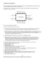
ED722 and ED726 Loop Driver Module (ED816A Variation)
-4-
ED816A Addressable Fire and gas detection Installation manual 8-9-08 Rev-a
Back up alarm / indicator lamps
EVACUATE MUTE
RESET
POWER
ALARM
PRE-ALM
DELAYED
FAULT
SILENCED
ISOLATED
LOOP 1 STATUS
EVACUATE MUTE
RESET
POWER
ALARM
PRE-ALM
DELAYED
FAULT
SILENCED
ISOLATED
LOOP 2 STATUS
Lamp Test button and backup Reset
button.
(See below for usage)
Lamp Test button and backup Evacuate
Lamp Test button and backup Mute
button.

