10 – Finishing the Assembly of the Protection PCB
●
21
Place and solder the small capacitors, the smallest ones first: C3, C10,
C11, C32, C4, C5, C12, C2, C13, C14, C18, C19, C29, C17, C33, C28.
Next, the larger/higher-value capacitors: C6, C7, C8, C9, C30, C31,
C34 , input terminal pins, C1.
10 – Finishing the Assembly of the
Protection PCB
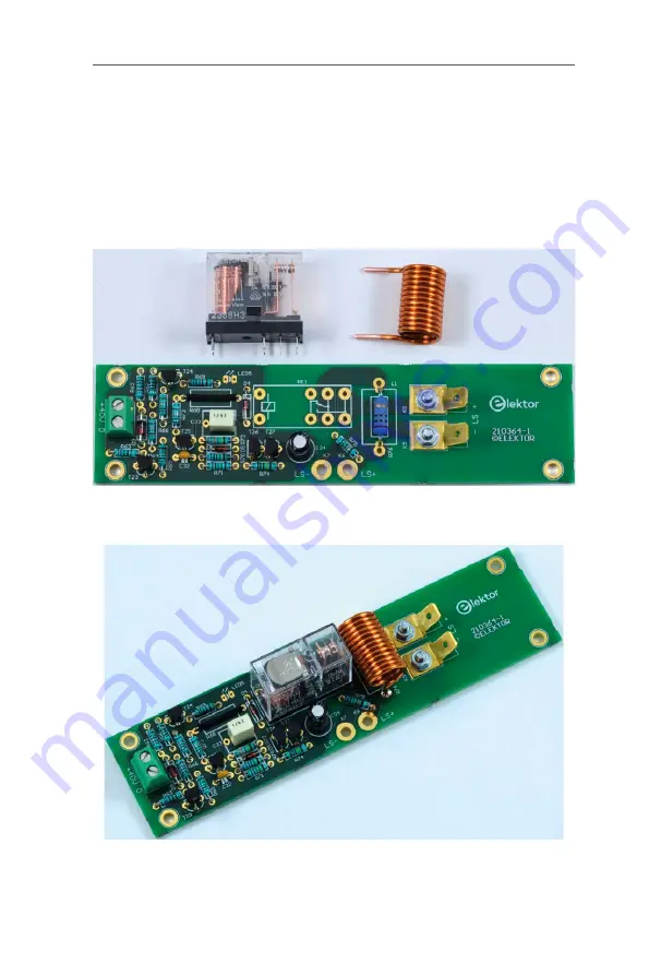
Figure 20. To finish the protection board, solder the
relay and the air-cored inductor onto the board.
Figure 21. The completed protection board
(PCB 210364-1 v1.1 shown).


