14 – The Output-Stage Transistors
●
27
14 – The Output-Stage Transistors
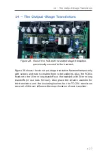
Figure 28. View of the PCB and the output stage transistors
provisionally secured to the heatsink.
Figure 28 shows the six output stage transistors fastened temporarily
with screws and nuts to enable them to be soldered. Also, the PCB is
fixed onto the 10-mm long standoffs on the heatsink with 30-mm long
standoffs (or use nuts for now). Also, place the ceramic washers for
the transistors and the insulating bushes for the TO-220 transistors
since all of this can influence the exact location of each transistor.


