72
© 2006, Elektro-Automatik GmbH & Co. KG
Irrtümer und Änderungen vorbehalten
EN
Instruction Manual
PSI 8000 3U Series
Date: 05-03-2012
Operating the device
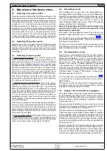
Remote control of current and voltage
Note: Remote control via analogue interface always requires
to put all
three
set values.
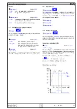
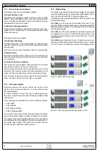
Two potentiometers between VREF and ground, sliders at the
inputs VSEL and CSEL. Power set value PSEL is tied to VREF
and thus set to 100%. The power supply can be controlled as
with the rotary knobs on the front and can either operate as
current or voltage source. In compliance with the max. 5mA
for the VREF output, potentiometers with at least 4.7kOhm
should be used.
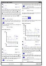
Alternatively, external voltage sources can be used to control
the set value input (second example).
or
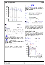
Remote control with power
Similiar to the example above, but with adjustable power limit.
11. Miscellaneous
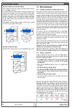
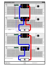
11.1 Parallel connection in Share bus mode
Share bus operation is used to gain a symmetric load current
distribution when running multiple units in parallel connection.
Important: in this operation mode, the unit with the highest output
voltage controls and defines the output voltage of the whole
parallel connection. It means, any unit of the system could be
in charge. Thus it recommended to pick a unit that is used to
control the whole system, while the set value of voltage for the
remaining units is set to the required minimum. Voltage and po-
wer set value could be set to 100% or, if not desired, set to equal
values on every unit so that the total results in what‘s required.
In case a unit is broken and will completely shut off, the parallel
connection will continue to work without interruption. This is
called redundancy.
For a device error like overtemperature (OT) or overvoltage,
the output voltage will rise or fall to the highest value that was
adjusted on any of the remaining units.
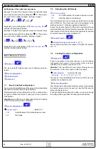
The wiring of terminal „Share“, which is required for Share bus
operation, is explained in section „5.8 Terminal „Share““. Also
see figure 13 below.
Note: if remote sense is going to be used, it is recommended
only to connect the „Sense“ input of the main unit that deter-
mines the system voltage.
Attention! This is a purely analogue connection. No totals
formation of actual values on any of the units.
Attention! Share bus connection with units different to
3U series, which also feature a Share bus, is not allowed!
11.2 Series connection
Series connection of two or more units is generally allowed.
But there are some restrictions and rules to consider because
of safety and isolation reasons:
•
No negative DC output pole of a unit in the series
connection may be raised to a potential >300V against
ground (PE)!
•
Every unit is adjusted seperately, there is no master-slave
connection.
•
The Share bus must not be wired!
•
The grounds (AGND, DGND) of the analogue interfaces
of the units in series connection must not be wired to
each other!
•
Remote sense must not be wired!
•
It is recommended to build a series connection only with unit
of same model.
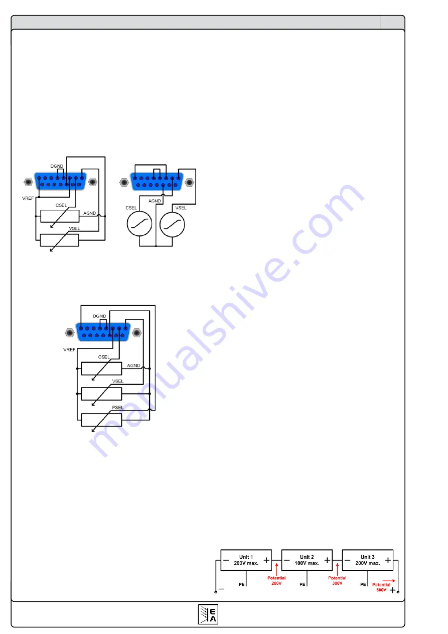
Example: Three identical units with 200V nominal voltage, for
example PSI 8200-70 3U, shall be connected in series. When
calculating, the total voltage of that series connection could go
up to 600V. Looking at the resulting potentials on the negative
outputs of the units, the 3rd unit negative DC pole could be
raised to 400V if all units put out maximum voltage. This is
not permitted! So one of the lower units has to be limited to a
certain maximum. The figure below clarifies that the resulting
total voltage would only be 500V:

