71
Instruction Manual
PSI 8000 3U Series
EN
Date: 05-03-2012
Operating the device
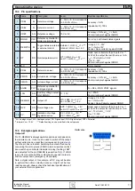
10.4 Pin specifications
Pin Name
Type* Description
Level
Electrical specification
1
VSEL
AI
Set value: voltage
0…10V or 0...5V correspond
to 0..100% of U
Nom
Accuracy < 0.2%
Impedance R
i
>100k
2
CSEL
AI
Set value: current
0…10V or 0...5V correspond
to 0..100% of I
Nom
3
VREF
AO Reference voltage
10V or 5V
Accuracy < 0.2% at I
Max
= +5mA
Short-circuit-proof against AGND
4
DGND
POT Reference potential for
digital control signals
For +Vcc, control and status signals
5
REMOTE
DI
Toggle between internal
or external control
External = LOW, U
Low
<1V ***
Internal = HIGH, U
High
> 4V
U range = 0 …30V
I
Max
= +1mA at 5V
Sender: Open collector against DGND
6
OT
DO Overtemperature error OT = HIGH, U
High
> 4V
no OT = LOW, U
Low
<1V ***
Quasi open collector with pull-up to Vcc **
At 5V at the output there will be max.+1mA
I
Max
= -10mA at U
CE
= 0.3V
U
Max
= 0...30V
Short-circuit-proof against DGND
7
N.C.
Not connected
8
PSEL
AI
Set value: power
0…10V or 0...5V correspond
to 0..100% of P
Nom
Accuracy < 0.5%
Impedance R
i
>100k
9
VMON
AO Actual value: voltage
0…10V or 0...5V correspond
to 0..100% of U
Nom
Accuracy < 0.2% at I
Max
= +2mA
Short-circuit-proof against AGND
10 CMON
AO Actual voltage: current 0…10V or 0...5V correspond
to 0..100% of I
Nom
11 AGND
POT Reference potential for
analogue signals
For -SEL, -MON, VREF signals
12 +Vcc
AO Auxiliary voltage output
(Ref: DGND)
11...13V
I
Max
= 20mA
Short-circuit-proof against DGND
13 REM-SB
DI
Output off
off = LOW, U
Low
<1V ***
on = HIGH, U
High
> 4V
U range = 0…30V
I
Max
= +1mA at 5V
Sender: Open-Collector against DGND
14 OVP
DO Overvoltage error
OVP = HIGH, U
High
> 4V
no OVP = LOW, U
Low
<1V ***
Quasi open collector with pull-up to Vcc **
At 5V at the output there will be max.+1mA
I
Max
= -10mA at U
ce
= 0.3V
U
Max
= 0...30V
Short-circuit-proof against DGND
15 CV
DO Indication of voltage
regulation active
CV = LOW, U
Low
<1V ***
CC = HIGH, U
High
>4V
* AI = Analogue input, AO = Analogue output, DI = Digital input, DO = Digital output, POT = Potential
** Internal Vcc = 13.8V *** Default setting, can be modified in the setup menu
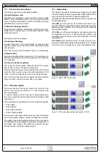
Clarification:
10.5 Example applications
Output off
Pin 13 „REM-SB“ is always operative and does not depend on
the remote mode . It can thus be used to switch off the output
without extra means, except the device was set to mode
local.
Then the pin has no function. Switching the output off is done by
connecting the pin to ground (DGND) via a low-resistive contact
like a switch, open collector transistor or relay, if setting „LOW“
was selected for the pin REM-SB (see section 10.3). If HIGH
is set, it is vice versa and the contact has to opened in order to
shut the output down (emergency off principle).
Note: a digital output of, for example, a PLC may not be able
to perform the action correctly, because it might not be low-
resistive enough. Always check the technical specifications of
your external control application.

