39
EN
Instruction Manual
EL 9000 HP Series
Date: 05-31-2011
6.10 Control locations and priorities
Control locations are the locations from where the device
is controlled. This can be at the device (manual control),
via the analogue interface (external control) or via a di-
gital interface card (remote control). In order to prevent
the user from accessing the device from two locations at
once there are priorities. Following applies:
The analogue interface has the highest priority, the digital
interface the second highest one and the manual control
the lowest one. It means, that if the device was set to re-
mote control, modes and set values can‘t be set with the
switches and rotary knobs anymore. If the device would
be switched to external control while remote control is
active, the remote control status would be reset and the
device would only be controllable via the analogue inputs.
In order to report this to a software running on a PC, still
trying to access and control the device, the control loca-
tion is internally set to „local“. In „local“ status the device
can only be read (i.e. monitored) by the PC.
6.11 Series and parallel connection
Parallel connection of multiple loads is possible, but it is
not explicitely supported. That means, there is no auto-
matic distribution of the current at parallel connection. The
user has to take care of the correct control of the devices.
When using parallel connection, the symmectric distri-
bution is achieved by adjusting the same set values for
U,I,P and R at any device via the control panel or the
interfaces (digital or analogue).
Attention! Series connection is not allowed! The
devices could be damaged
.
Handling the device
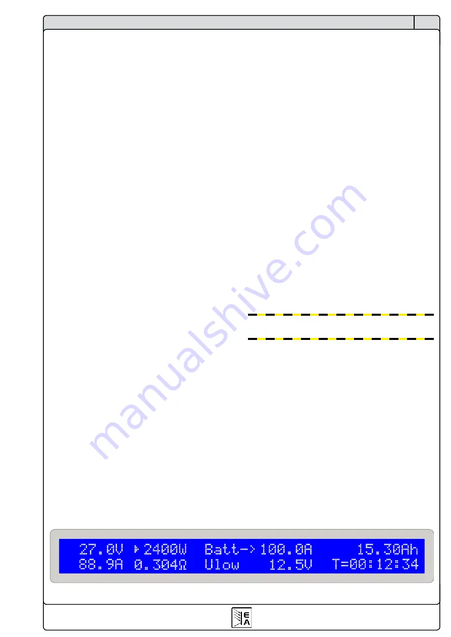
Figure 13. Battery test operation in current control (CC) mode
Note:
if the regulation mode is changed by
Mode(2)
, all
other set values that are not adjustable for the selected
regulation mode are set to default values in order to let
the test mode work correctly. Hence the setting
Keep set
values
is ineffective here.
The example in figure 13 shows that the current of 100A
can not be reached because the power limitation has
become active (example of a 2400W model).
A note about the time display
The time display is not 100% exact. The deviation of the
displayed time to the actually elapsed time can be 1-2
seconds per hour.
6.9 Alarm management
The alarm management consists of two parts: once, the
most recent alarm will be indicated and remaining on the
display (see figure 7.2) until it is acknowledged by the
user and twice, up to three different alarms are stored in
an internal error buffer. Since the first occured alarm is
considered as important, it is pushed to the end of the
error buffer if more alarms occur, but not overwritten.
If the buffer is full, the last entry is overwritten by any
recent alarm as long as the buffer is not read out by a
command using a digital interface card. Reading the
buffer will empty it and also automatically acknowledge
alarms indicated on the display.
The error buffer stores an error code and a status code for
every of the three possible entries, telling the user if the
alarm is still active or already gone. More information is
contained in the instruction manual of the interface cards.
The display also indicates the status of the indicated
alarm. The reason is to tell the user that one or multiple
alarms have occured during his absence, especially if
the alarm only lasted for a very short period of time,
like overvoltage cause by spikes. The user has to either
acknowledge that he has noticed the alarm indication
by pressing the
Input on/off(4)
button or by reading the
error buffer via communcation.
Note:
Alarms that occur during remote or external control
are not indicated on the display, because of the control
mode status indication. Thus they only need to be ack-
nowledged when leaving those modes or not at all if the
error has been read before by command.
Summary of Contents for 33200246
Page 2: ......
Page 7: ...7 CN EL 9000 HP 系列 产品说明书 日期 05 31 2011 关于产品 3 外观 3 1 前视图 图 1 ...
Page 8: ...8 CN EL 9000 HP 系列 产品说明书 日期 05 31 2011 关于产品 3 2 后视图 图 2 ...
Page 24: ......


