41
EN
Instruction Manual
EL 9000 HP Series
Date: 05-31-2011
Handling the Gerätes
CAN Baud rate
Possible settings:
10kBd
,
20KBd
,
50kBd
,
100kBd
,
125kBd
,
250kBd
,
500kBd
,
1MBd
Default setting:
100kBd
Belongs to: CAN interface card IF-C1
Explanation: determines the baudrate (transmission
speed) of the CAN bus. If you connect the CAN card to
an existing network, you got to set the same baudrate
here as the bus is using, becaus any device in a bus has
to use the same bus speed.
CAN Relocatable ID
Possible settings:
0
...
31
Default setting:
0
Belongs to: CAN interface card IF-C1
Explanation: this determines the (relocatable) address
segment, in which the device node of the CAN is located.
For further information refer to basic CAN topology datas-
heets.Example: if the electronic load has to be assigned
to address 5 by certain reasons and this would collide
with another bus member with the same address, you can
move the address to another segment by defining the RID
(short for relocatable ID), so that no collision can occur.
Hence there are, theoretically, 32 x 30 possible device
nodes available when using CAN.
CAN Bus terminate
Possible settings:
yes
,
no
Default setting:
no
Belongs to: CAN interface card IF-C1
Explanation: defines, if the bus termination resistor on the
CAN interface card is active or not. This is only required if
the CAN card is in that particular device which is located
at the end of a CAN bus. By setting this parameter to
yes
the resistor is activated,
no
deactivates it. In case you
don‘t want to use this feature and instead want to install
a custom resistor for bus termination, make sure that this
setting is set to
no
.
RS232 Baud rate
Possible settings:
9600 Bd
,
19200 Bd
,
38400 Bd
,
57600 Bd
Default setting:
57600 Bd
Belongs to: RS232 interface card IF-R1
Explanation: determines the baudrate (transmission
speed) of the serial data transmission when using the
serial RS232 interface card IF-R1. Make sure, that the
other end of the serial connection operates at the same
baudrate.
7. Device configuration
7.1 The setup menu
The setup menu can activated anytime by the selector
Level(3)
, except during remote control mode (by interface
card) or external mode (analogue interface). While the
load is in setup, no normal load operation is possible.
The display shows a certain number of parameters,
depending on which interface card is installed. The pa-
rameters are selected by
Selection(5)
and changed with
Setting(6)
. Two small triangles on the right side of the
display indicate that multiple parameters are available.
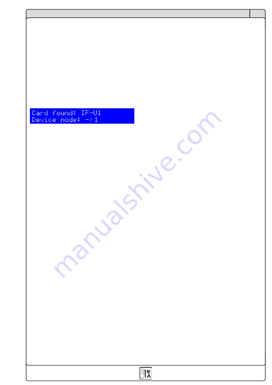
The display furthermore shows the type string of the
installed card in the first line, for example
IF-U1
, if one
is equipped:
Figure 15
The second line subsequently shows all parameters
which are selected by
Selection(5)
. The number of
parameters varies according to the equipped interface
card. The following overview lists the possible parameter
and its settings:
Trigger mode
Possible settings:
internal, external
Default setting:
internal
Belongs to: Device
Explanation: defines, if the trigger signal for the Level A/B
operation, which effects the change between A and B, is
automatically generated by the device (
internal
) or if it‘s
put in by the trigger input (
external
).
Device node
Possible settings:
1
...
30
Default setting:
1
Belongs to: Device
Explanation: defines the device node (or address) of the
device in order to distinct between mutliple devices in
a network and to address it correctly. 30 addresses are
available which means that up to 30 devices can be con-
trolled from one PC. Every address must only be given
once in a system of connected devices.
Keep set values
Possible settings:
yes
,
no
Default setting:
no
Belongs to: Device
Explanation:
yes
defines, that the set values which are
adjusted by the user are kept when switching the regu-
lation mode (also see „6.6 Preselecting the regulation
mode“), while
no
defines that the set values are always
reset to default values when switching.
Summary of Contents for 33200246
Page 2: ......
Page 7: ...7 CN EL 9000 HP 系列 产品说明书 日期 05 31 2011 关于产品 3 外观 3 1 前视图 图 1 ...
Page 8: ...8 CN EL 9000 HP 系列 产品说明书 日期 05 31 2011 关于产品 3 2 后视图 图 2 ...
Page 24: ......


