32
EN
Instruction Manual
PSI 800 R Series
Date: 01-25-2016
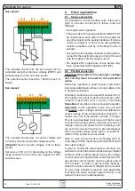
Set values 1
The example shows how the set values can be
controlled using the reference voltage (VREF) and
potentiometers on the set value inputs.
The potentiometer should be 10kOhm each or
higher.
Set values 2
The example shows how to control voltage and
current by means of external voltage sources.
Attention!
Never connect voltages >12V to these
inputs!
Set values >10V or >5V, depending on the voltage
range selection in the setup, are clipped to 100%
nominal value.
Handling the device
6. Other applications
6.1 Series connection
It is possible to connect multiple units of the same
type to a series connection if these rules are
followed:
• No master-slave operation
• The grounds of the analog interfaces MUST NOT
be connected to each other. This also applies for
any other signal on the analog interfaces. If remote
control is required, it can be done using galvanic
isolation amplifiers and by controlling all units in
parallel.
• Any load current leading conductor must be dimen-
sioned for the maximum output current of the unit
with the highest nominal output current.
• No negative DC output pole of any device may
have a potential >300V against earth (PE).
6.2 Parallel connection
Attention! Only units of the same type (voltage
and current) must be used for this operation
mode.
Share bus operation is used to gain a symmetric
load current distribution when running multiple units
in parallel connection.
Following connections are required: connect all (+)
DC outputs of the units to each other and all (–) DC
outputs to each other. Pins (+) and (-) of terminal
Share Bus
of all units are also connected in parallel.
Important
: in this operation mode, the unit with
the
lowest
output voltage controls and defines the
output voltage of the whole parallel connection. It
means, any unit of the system could be in charge.
Thus it recommended to pick one unit that is used
to control the whole system, while the set value of
voltage, current and power for the remaining units
are set to the required maximum. All units displays
their own actual values, there will be no totals for-
mation of the system‘s actual values.
Note: in case of an error like overheating (OT) or
overvoltage (OVP), the whole system will shut down
the output voltage.
In order to control the whole system remotely, it is
sufficient to control the master via its analog or digital
interface. When reading actual values, the voltage
monitor value will represent the overall system volt-
age, but the current monitor only the output current
of the master. In order to get accurate readings,
either the actual current is multiplied by the number
of units in the parallel connection (only applicable
if all have the same nominal output current) or all
units will have to be read separately.


